If you type “ESP32-CAM” in to your preferred internet search engine, you’ll likely come across the development board entitled “AI-Thinker” pictured here, which typically features a “2MP” camera, an ESP32-S dual core microprocessor and 8MB of PSRAM.
I’ve used this development board extensively to do projects such as showing a live video stream on various displays, doing on-board edge detection, and going as far as making an augmented reality shooting game.
This write up is a guide on the various tricks and tips such as:
Please note that this page doesn’t cover the WiFi or other wireless technologies, and is geared more to operating the camera sensor.
Pinout & Hardware Constraints
The ESP32 has 34 physical GPIO pins, however camera module takes up most them. The remaining pins are then gobbled up by the onboard SD card, flash LED, status LED and PSRAM leaving none for any external peripherals.
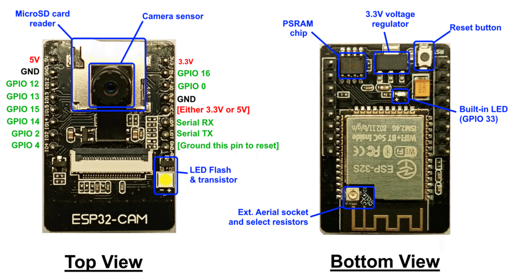
However, with some compromises it is possible to use some of the GPIO pins for other purposes. The following table shows what pins are available, and at what cost.
| Pin Label | Function |
|---|---|
| 5V | Power in from 5V source |
| GND | Ground to power source |
| GPIO 12 | Used by SD card Otherwise available as GPIO |
| GPIO 13 | Used by SD card Otherwise available as GPIO |
| GPIO 15 | Used by SD card Otherwise available as GPIO |
| GPIO 14 | Used by SD card Otherwise available as GPIO |
| GPIO 2 | Used by SD card Otherwise available as GPIO |
| GPIO 4 | Connected to the flash LED Otherwise available as GPIO, flash will turn on when pulled low |
| 3.3V | 3.3V output from regulator |
| GPIO 16 | Connected to PSRAM chip select Otherwise available as GPIO |
| GPIO 0 | Pulled low on restart = download mode |
| VCC | Either 3.3V or 5V output depending on some resisitors |
| U0R | Serial RX (UART 0) used for uploading programs |
| U0T | Serial TX (UART 0) used for uploading programs |
| GND/R | Connect to ground to restart ESP32 DO NOT USE AS GROUND |
| Built-in LED (GPIO 33) | With some hardware modifications, it is possible express this pin as GPIO. Full instructions on this page. |
Camera Modules
There are a number of different camera sensors available, all with 24 pin ribbon cables, so you would be forgiven to think that they’re all interchangeable, however, this is not true in all cases.
OV2640
This is a “2MP” UXGA 1600×1200 pixel sensor by Omnivision [datasheet] and is the typical sensor with the AI-Thinker board.
The OV2640 outputs a number of formats including RGB565, YUV422 and JPEG.
RHYX-M21-45
This is another “2MP” 1616×1232 pixel sensor which often comes with the AI-Thinker board. Please note that this sensor does not support JPEG output.
More information on this sensor can be found on this page.
OV5640
Often marketed as a 5MP alternative to the OV2640, and while pin ‘compatible’, there is a miss-match with the voltage levels causing the sensor to overheat very quickly. [datasheet]
I would not recommend using the OV5640 sensor with the AI-Thinker.
Regardless of what sensor you get, if you’re intending on continual use or JPEG encoding then I would recommend considering cooling. Affixing the rear of the sensor to the SD card with some thermal paste & super glue usually does the trick, some sensors come with a self adhesive pad for this reason.
Uploading Code
The astute observer will note that the AI-Thinker ESP32-CAM development board lacks any USB port to connect to your computer, so you need another piece of hardware to provide this connection. Below are three different methods, each with their pros and cons. This doesn’t include over-the-air wireless updates, as this still requires a physical USB to upload the initial program.
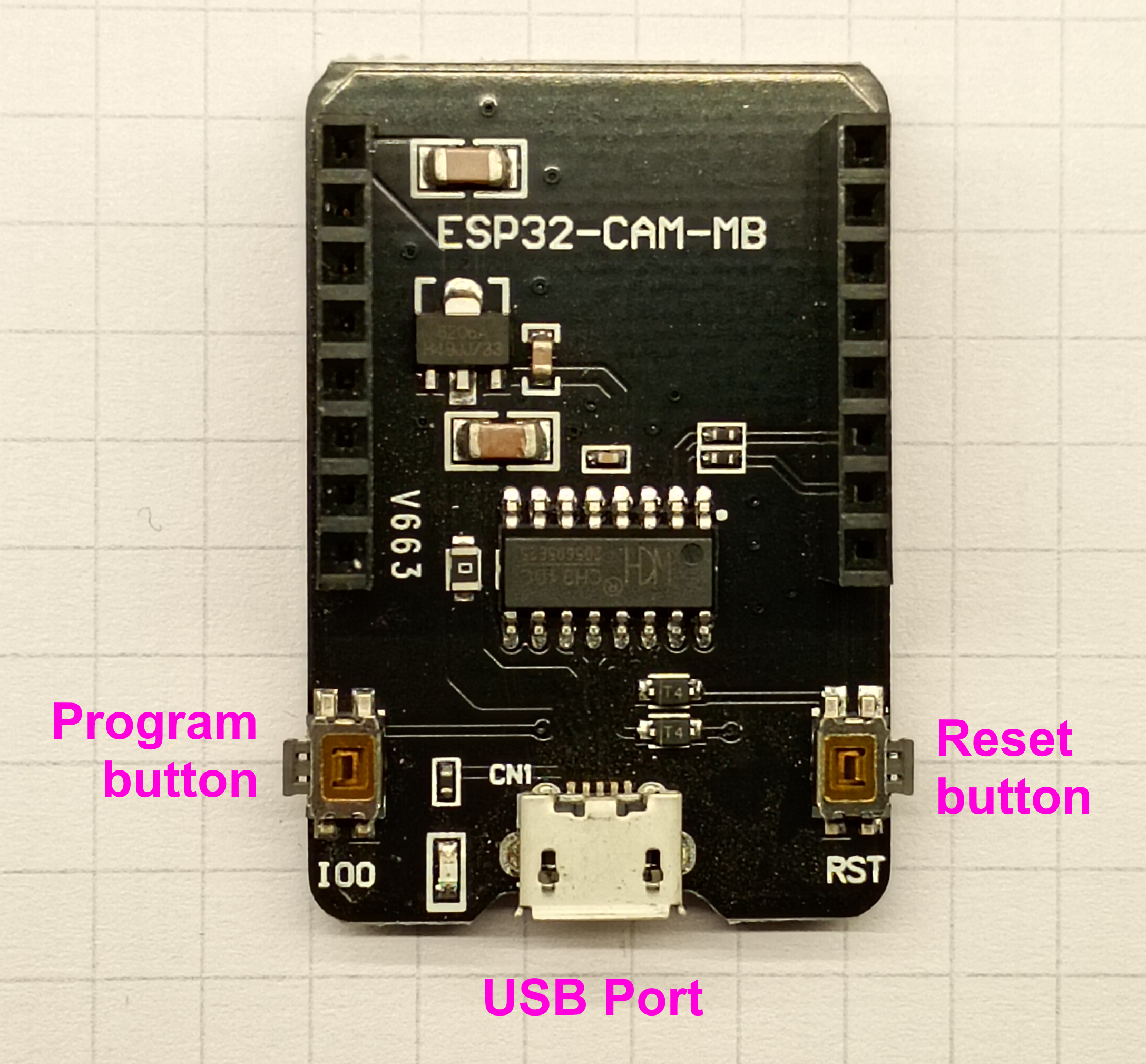
ESP32-CAM-MB Board
Most AI-Thinker boards come with the ‘MB’ board, or offer it as an extra. This method is the simplest in that you insert the pins of the ESP32-CAM into the corresponding socket.
The MB board comes with a USB port with CH340 USB chip and two a momentary switches: one for a reset button, and the other to enter boot mode.
The main downside to using these adapters is that you cannot easily connect any peripherals. This may not be a problem for your application.
I would also like to note that I’ve experienced high levels of quality issues with these ‘MB’ boards.
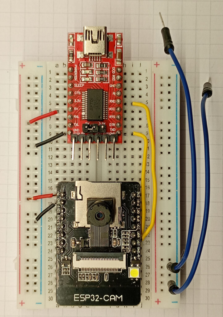
FTDI TTL Adapters
Another common method for programming the ESP32-CAM is using an FTDI TTL to USB adapter.
These usually come with a set of male headers at the rear, and can be attached with F-F jumper leads. However, I would recommend soldering male pins along the two rows and inserting it in to a breadboard with the ESP32-CAM.
Ensure the voltage selection jumper is on 5V, and wire the ESP32-CAM with the FTDI as this:
- FTDI 5V –> ESP32CAM 5V
- FTDI GND –> ESP32CAM GND
- FTDI RXD* –> ESP32CAM TX (U0T)
- FTDI TXD* –> ESP32CAM RX (U0R)
- (Only when uploading code) GND –> ESP32CAM GPIO 0 (IO0)
As the reset button is not accessible, I would recommended to use two additional grounding leads, one to tap the GND/R pin to reset, and the other to connect to pin 0 to ground to put the chip in to uploading mode.
*Ensure that the pins are RXD & TXD, not RXL or TXL – these only connect to the TX/RX LEDs.
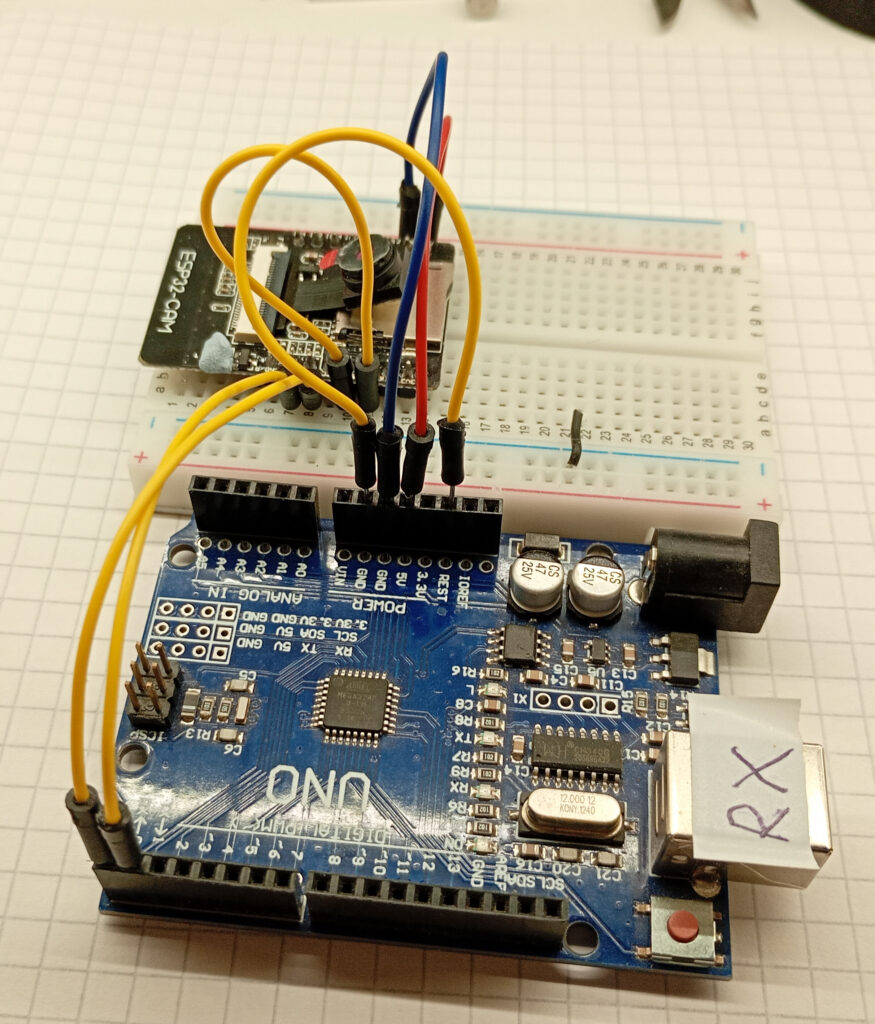
Using an Arduino as a UART Bridge
If you have neither of the above, then it is possible to program an ESP32-CAM via an Arduino by piggy-backing off it’s USB to serial converter, however it’s worth noting that the upload speeds are very slow.
The connection between the ESP32-CAM and Arduino is as follows:
- Arduino 5V –> ESP32CAM 5V
- Arduino GND –> ESP32CAM GND
- Arduino RX –> ESP32CAM RX (U0R)*
- Arduino TX –> ESP32CAM TX (U0T)*
- Arduino Reset –> GND
- (Only when uploading code) GND –> ESP32CAM GPIO 0 (IO0)
*Note that the RX/TX pairs are not swapped. This is swap is already done on the Arduino.
Board Settings
I’m using the Arduino IDE for this; specifically version 1.8.19. This assumes you have already installed the ESP32 boards to your preferred IDE. The board settings are different between using the MB board or FTDI adapter compared to an Arduino.
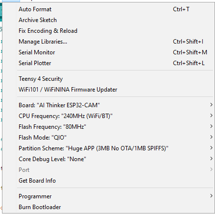
Settings for MB Board or FTDI Adapter
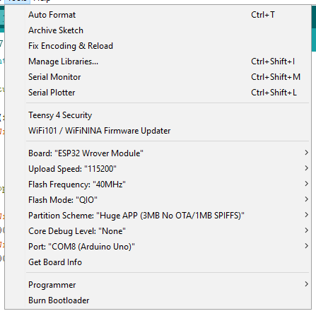
Settings for Arduino as Programmer
Testing & Troubleshooting
Test Serial Connection
With all of the hardware connected, plug the USB in to the computer, select the correct com port and open the serial monitor.
For the case of the FTDI and Arduino setup, ensure GPIO 0 is connected to ground and reset the ESP32CAM by momentarily connecting GND/R to ground.
If you’re using the MB board then hold down the IO button while monetarily pressing the RST button (you can then let go of all buttons at that point…)
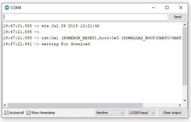
In either case, if you can read “waiting for download” on the serial monitor, then you have a working serial connection.
Blink (With a Flash)
Building on the above; this code can be uploaded to check if the onboard LED flash light works, thus confirming that you can successfully upload programs to your ESP32CAM.
Please note: this is a bright light! I would recommend covering the LED with something opaque (eg. electrical tape or blu-tac).
During the upload process, do not press any buttons. The size of the sketch will determine how long the upload time is: if you’re using an Arduino as an ISP then the web server example will take over 2mins to load.
After uploading the code, remove the connection between GPIO 0 and ground, and then restart the ESP32. For MB board users, simply press the RST button.
const int flash_pin = 4;

void setup() {

pinMode(flash_pin, OUTPUT);
digitalWrite(flash_pin, LOW);

}

void loop() {

digitalWrite(flash_pin, HIGH);
delay(500);
digitalWrite(flash_pin, LOW);
delay(500);

}
But what if it doesn’t?
In the likely event that some part of the above does not work, start from the beginning and try and isolate the fault.
- Check the voltage of the 5V and 3.3V lines with a multimeter. If you’re not reading the correct voltages then you have a power supply problem.
- If you don’t see the “waiting for download” then there is a problem with the serial connection. Check all your wiring, noting whether the RX/TX pairs should be swapped or not. Check the baud rate on the serial monitor is set to 115200. Also check that your USB cable can handle data transmission (not just power).
- If you get an error message above the serial port being busy then close down all serial monitor screens and try again.
- If you still get uploading errors pertaining to serial ports then double check all board settings (especially upload speed and baud rate), and if that doesn’t work then turn your computer off and try again.
- If you’re still struggling then drop me a message on the contact page and I’ll see if I can replicate and fix.
Accessing The Sensor Data
While the datasheet for the sensor gives all of the pertinent information in regards to accessing and modifying the relevant registers, to access that sweet data. Thankfully the “esp_camera.h” library adds a layer of abstraction, and takes a two dimensional image of variable colour, and outputs a one-dimensional array of pointers.
Pixel Structure & Data Format
It is important to know how the data is structured in order to understand the output as the camera takes a two-dimensional image of a variable colour, and outputs a one-dimensional byte array.
Pixel Format
The bit structure of a single pixel within the byte array will depend on the output format.
An 8-bit greyscale pixel will consist of a single byte with a total of 256 different shades of grey, ranging from binary 00000000 to 11111111 (decimal 0-255).
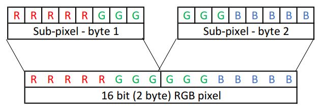
A 16-bit RGB565 pixel will consist of two bytes and is able to achieve 65,536 different colours. The structure of the pixel is shown below.
It is important to note that a 16-bit image will require double the amount of memory – an 8-bit QVGA image is 76.8kB, while a 16-bit RGB QVGA image is 153.6kB.
Due to a “technical limitation” noted in the espressif documents for the ESP32, only 160kB of DRAM is available, leaving a meagre 6.4kB left for anything else. If you’re getting constant boot loops with guru mediation panic errors, then it’s probably stack overflow.
It is possible to circumvent the memory overflow errors, by utilising the PSRAM on the AI-Thinker boards.
Addressing Pixels.
The position of the pixel along the byte array will correlate to the X & Y co-ordinates of the pixel in the image.
Calculating the co-ordinates requires knowing the width of the resolution and is done with two equations:
- X co-ordinate = remainder value when the array location is divided by the resolution width.
- Y co-ordinate = integer value when the array location is divided by the resolution width.
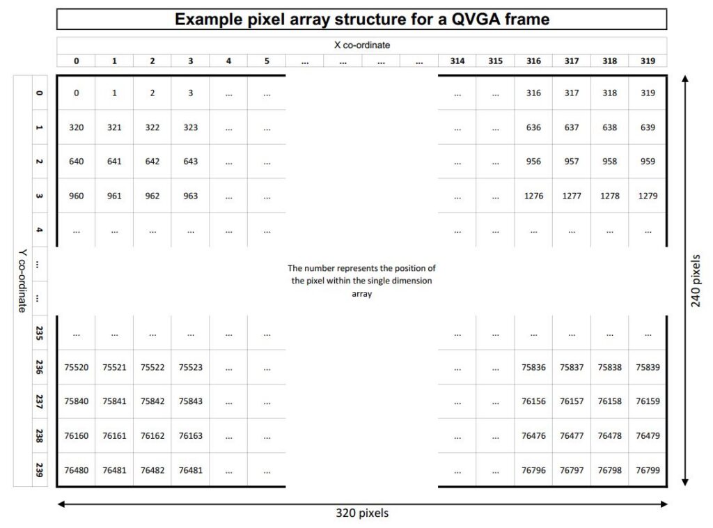
The code to achieve this is fairly, simply due to the implied integer division and modulo function.
x_position = array_number % resolution_width

y_position = array_number / resolution_width
Basic Test Code
The best way to explain something is to show an example; so the below returns the colour values of the centre-most pixel. As this is using the RGB565 colour scheme, the maximum value of the red and blue channels is 31, while the green maxes out at 61.
Libraries, Definitions and Globals
The SPI and camera libraries are required. Ensure that the correct pins are defined for your camera.
These values are typical for an AI-Thinker.
#include "esp_camera.h"
#include <SPI.h>

#define CAMERA_MODEL_AI_THINKER
#define PWDN_GPIO_NUM     32
#define RESET_GPIO_NUM    -1
#define XCLK_GPIO_NUM      0
#define SIOD_GPIO_NUM     26
#define SIOC_GPIO_NUM     27
#define Y9_GPIO_NUM       35
#define Y8_GPIO_NUM       34
#define Y7_GPIO_NUM       39
#define Y6_GPIO_NUM       36
#define Y5_GPIO_NUM       21
#define Y4_GPIO_NUM       19
#define Y3_GPIO_NUM       18
#define Y2_GPIO_NUM        5
#define VSYNC_GPIO_NUM    25
#define HREF_GPIO_NUM     23
#define PCLK_GPIO_NUM     22

camera_config_t config;

int n_elements = 57600;
long initalTime = 0;
long frameTime;
Setup( ) and Camera Settings
The camera is configured in this section.
The available frame sizes which I have tested are:
- FRAMESIZE_240x240
- FRAMESIZE_CIF
- FRAMESIZE_QVGA
- FRAMESIZE_VGA
- FRAMESIZE_SVGA
A previous experiment was attempted using UXGA but errored due to the size.
The available pixel formats that I have tested are:
- PIXFORMAT_RGB565
- PIXFORMAT_GRAYSCALE
I’ve not played around with the sensor settings, aside changing the special_effect on the fly when developing a graphical user interface.
void setup() {
  psramInit();

  config.ledc_channel = LEDC_CHANNEL_0;
  config.ledc_timer = LEDC_TIMER_0;
  config.pin_d0 = Y2_GPIO_NUM;
  config.pin_d1 = Y3_GPIO_NUM;
  config.pin_d2 = Y4_GPIO_NUM;
  config.pin_d3 = Y5_GPIO_NUM;
  config.pin_d4 = Y6_GPIO_NUM;
  config.pin_d5 = Y7_GPIO_NUM;
  config.pin_d6 = Y8_GPIO_NUM;
  config.pin_d7 = Y9_GPIO_NUM;
  config.pin_xclk = XCLK_GPIO_NUM;
  config.pin_pclk = PCLK_GPIO_NUM;
  config.pin_vsync = VSYNC_GPIO_NUM;
  config.pin_href = HREF_GPIO_NUM;
  config.pin_sscb_sda = SIOD_GPIO_NUM;
  config.pin_sscb_scl = SIOC_GPIO_NUM;
  config.pin_pwdn = PWDN_GPIO_NUM;
  config.pin_reset = RESET_GPIO_NUM;
  config.xclk_freq_hz = 20000000;
  config.frame_size = FRAMESIZE_240X240;
  config.pixel_format = PIXFORMAT_RGB565;
  config.grab_mode = CAMERA_GRAB_LATEST;
  config.fb_location = CAMERA_FB_IN_PSRAM;
  config.jpeg_quality = 12;
  config.fb_count = 2;

  esp_err_t err = esp_camera_init(&config);

  sensor_t * s = esp_camera_sensor_get();
  s->set_brightness(s, 0);     // -2 to 2
  s->set_contrast(s, 0);       // -2 to 2
  s->set_saturation(s, 0);     // -2 to 2
  s->set_special_effect(s, 0); // 0 to 6
  s->set_whitebal(s, 1);       // 0=disable, 1=enable
  s->set_awb_gain(s, 1);       // 0=disable, 1=enable
  s->set_wb_mode(s, 0);        // 0 to 4 - if awb_gain enabled
  s->set_exposure_ctrl(s, 1);  // 0=disable, 1=enable
  s->set_aec2(s, 0);           // 0=disable, 1=enable
  s->set_ae_level(s, 0);       // -2 to 2
  s->set_aec_value(s, 300);    // 0 to 1200
  s->set_gain_ctrl(s, 1);      // 0=disable, 1=enable
  s->set_agc_gain(s, 0);       // 0 to 30
  s->set_gainceiling(s, (gainceiling_t)0);  // 0 to 6
  s->set_bpc(s, 0);            // 0=disable, 1=enable
  s->set_wpc(s, 1);            // 0=disable, 1=enable
  s->set_raw_gma(s, 1);        // 0=disable, 1=enable
  s->set_lenc(s, 1);           // 0=disable, 1=enable
  s->set_hmirror(s, 0);        // 0=disable, 1=enable
  s->set_vflip(s, 0);          // 0=disable, 1=enable
  s->set_dcw(s, 1);            // 0=disable, 1=enable
  s->set_colorbar(s, 0);       // 0=disable, 1=enable

  Serial.begin(115200);
  delay(1000);
}
Loop( ) part 1: Image aquisition
This section of code allocates space on the PSRAM for the image as an unsigned 16-bit array.
“camera_fb_t * fb = NULL” creates the camera buffer and sets it to all zeros. The “esp_camera_fb_get()” then populates this buffer with the image data.
The for loop converts the frame buffer to 16-bit elements by smoshing the two bytes together.
void loop() {
  initalTime = millis();

  //allocate space on PSRAM
  uint16_t *frame_buffer = (uint16_t *) ps_malloc(n_elements * sizeof(uint16_t));

  //take picture
  camera_fb_t  * fb = NULL;
  fb = esp_camera_fb_get();

  //Transfer camera buffer to buffer in PSRAM
  for (int i = 0; i < 57600; i++) {    //240x240px = 57600
    //create 16 bit colour from two bytes.
    byte first_byte = fb->buf[i * 2];
    byte second_byte = fb->buf[i * 2 + 1];
    frame_buffer[i] = (first_byte << 8) + second_byte;
  }
Loop( ) part 2: Analysis & reporting
The second part of the loop takes these 16-bit elements and deconstructs them into their constituent red, green & blue parts by bit-shifting and applying a bit-mask.
The esp_camera_fb_return(fb) is needed to free up the buffer, and the free(frame_buffer) releases the memory back to the PSRAM.
The results of the centre most pixel are shown on the serial monitor along with the time taken to process.
  //analyse centre pixel (number 28800 of 57600), and report colour values
  uint16_t R = (0b1111100000000000 & frame_buffer[28800]) >> 11;
  uint16_t G = (0b1111110000000000 & (frame_buffer[28800] << 5)) >> 10;
  uint16_t B = (0b1111100000000000 & (frame_buffer[28800] << 11)) >> 11;

  esp_camera_fb_return(fb);   //return the frame buffer back to the driver for reuse
  free(frame_buffer); //free up section of PSRAM

  frameTime = millis() - initalTime;
  Serial.println("Centre pixel colour:");
  Serial.print("R: ");  Serial.println(R);
  Serial.print("G: ");  Serial.println(G);
  Serial.print("B: ");  Serial.println(B);
  Serial.print("Image process time(ms): ");
  Serial.println(frameTime);
}
This program is inefficient for the sole reason of demonstrating the process of how to obtain an image and manipulate the data.
Page created: 23/05/2026
Last updated: