Sometimes, all it takes is a comment on Reddit to spark an idea that will send you on a journey of discovery and learning.
In this instance, the comment was on a post a previous ESP32CAM & ILI9341 setup[insert link], and they asked if it is possible to create a GUI with this hardware.
As I literally had the hardware wired up and ready to experiment, I couldn’t help but see this as a challenge.
This writeup goes through the the various hardware and software stages required to recreate the demo in the video, including all wiring and code.
Hardware – Modifications
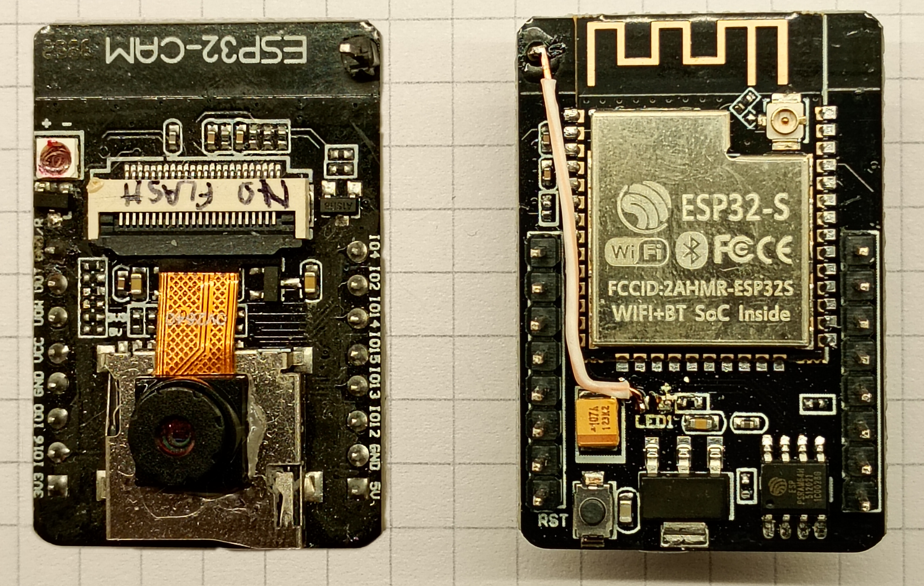
The AI-Thinker ESP32CAM is famously short of available GPIOs for peripherals, so the board will require modifications to sacrifice the onboard LED flash and status LED to drive the touch screen. The onboard SD card reader is off-limits, too.
GPIO 04 – Disabling LED Flash (Optional)
This is an optional step: without this modification the setup will work, but the LED flash light will be permanently illuminated and will cause strain on your eyes as well as use more power.
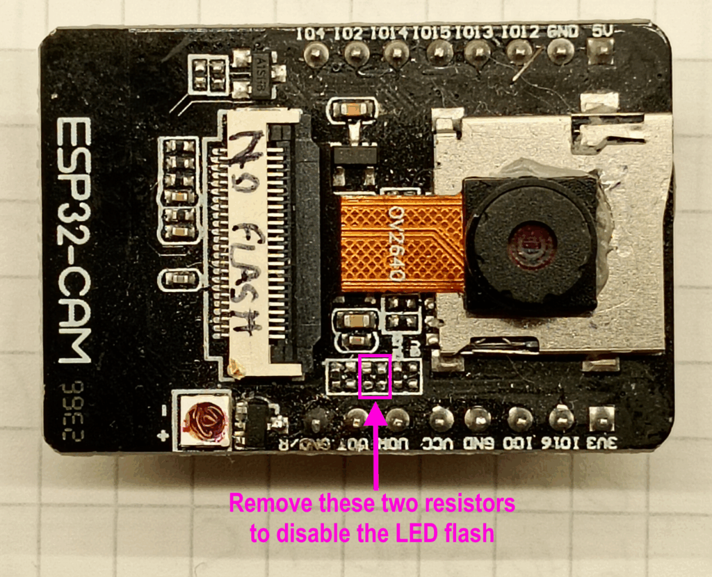
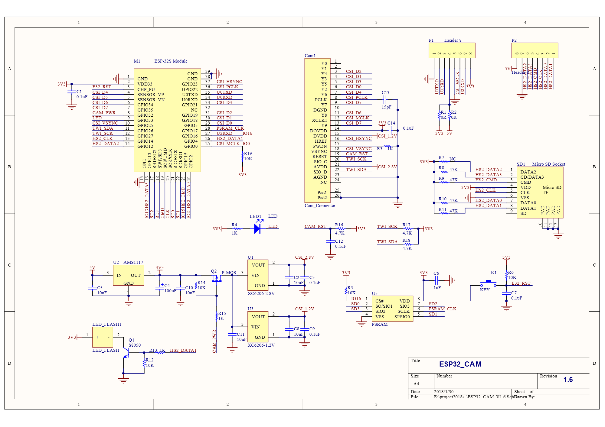
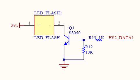
The schematic diagram of the ESP32-CAM shows that there is a 1k ohm bias resistor (R13) connected to the base of the transistor that drives the LED. There is also a 10k ohm pull down resistor (R12).
Removing R13 will disable the flash, unfortunately I was unable to determine the difference between R13 and R12 on the AI-Thinker, only that they both connected to the base of the transistor. So, I removed both to be sure.
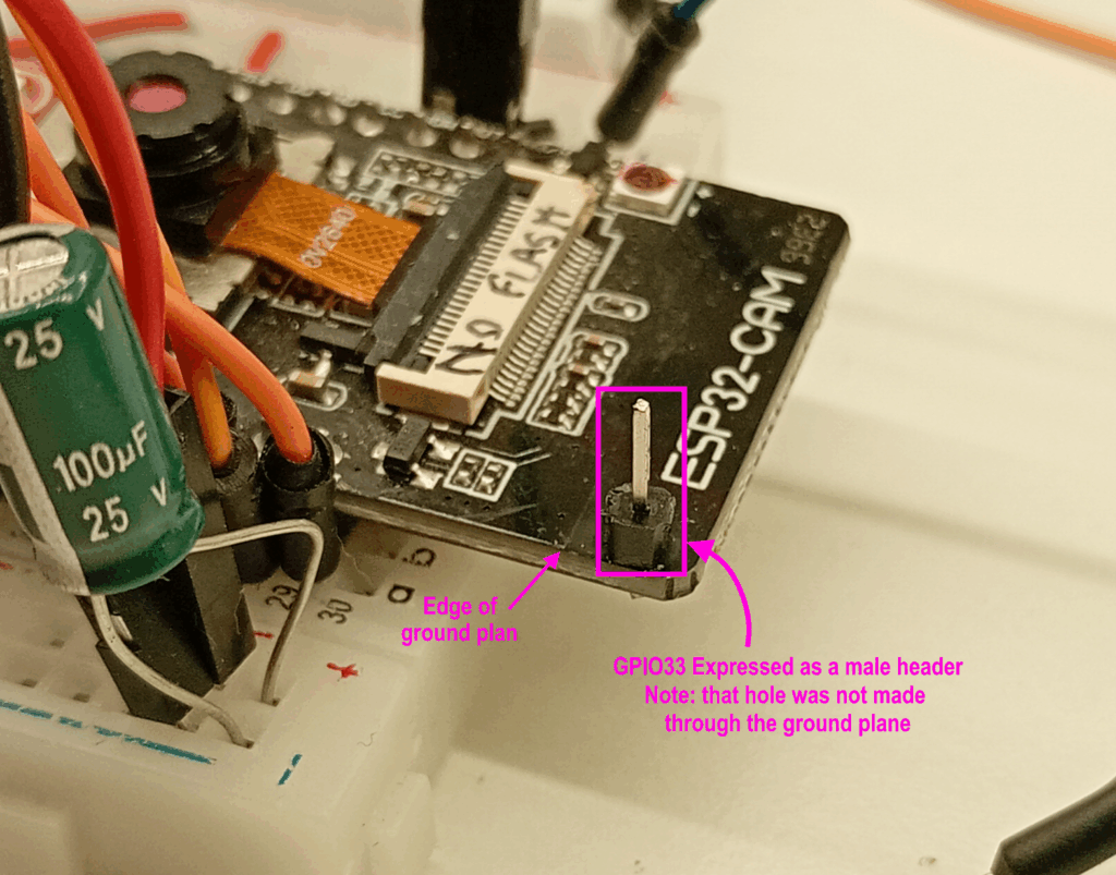
GPIO 33 – Disabling the Inbuilt LED and Exposing
This modification sets to relinquish the duties of GPIO 33 from the repressive role of the onboard LED and repurpose it as a useable I/O pin.
To begin, drill a small hole through the AI-thinker board, making sure to stay clear of the ground plane and PCB antenna. I used a 0.9mm micro drill bit, but this will depend on your pin dimensions.
As there are no pads to solder, the male header pin needs to be superglued in place for structural rigidity. Take note on which side to affix the header pin.
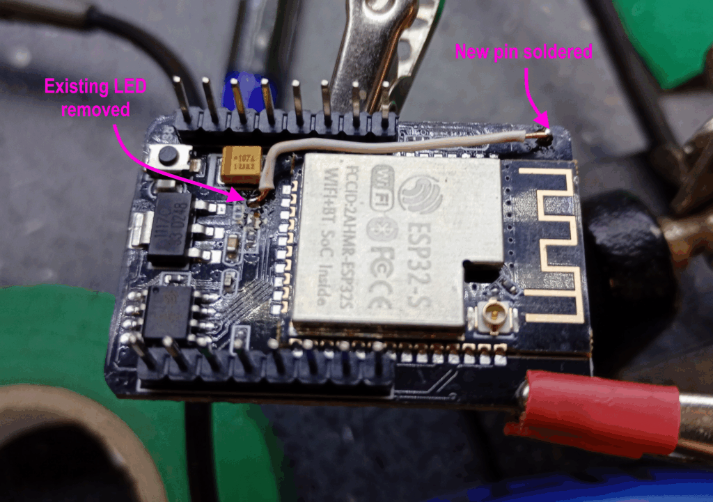
Annoyingly the schematic for the ESP32-CAM doesn’t include the circuit for this subsystem, however, after some rummaging with a multimeter, it was possible to determine that the cathode of the LED is connected to ESP32-S GPIO33.
Therefore to access the GPIO, de-solder the LED from the board and connect the newly glued header pin to the negative pad of the LED. In this instance I have used a core from some CAT5e cable – so quite literally patched.
Hardware – Wiring
Now with the modified AI-thinker board ready, it’s time to couple it with the TFT display and touchscreen controller.
This setup uses the 3.2inch version of the ILI9341 TFT display and XPT2046 resistive touch sensor with SPI connectivity.
Please note that this has not been tested with a capacitive touch sensor, nor parallel display connection.
There is also an external FTDI adapter (not shown in the photograph), which is used as the TTL to USB converter connected to the computer to enable the code to be uploaded.
The full list of connections are as follows:
- ILI9341 VCC to ESP32CAM 3.3V
- ILI9341 GND to ESP32CAM GND
- ILI9341 CS to ESP32CAM GPIO 02
- ILI9341 Reset to ESP32CAM GPIO 15
- ILI9341 DC to ESP32CAM GPIO 12
- ILI9341 SDI/MOSI to ESP32CAM GPIO 13
- ILI9341 SCK to ESP32CAM GPIO 14
- ILI9341 LED to ESP32CAM 5V
- ILI9341 SDO/MISO to ESP32CAM GPIO 33 (new pin)
- ILI9341 T_CLK to ILI9341 SCK
- ILI9341 T_CS to ESP32CAM GPIO 04
- ILI9341 T_DIN to ILI9341 SDI/MOSI
- ILI9341 T_DO to ILI9341 SDO/MISO
- (ILI9341 T_IRQ is not connected)
- FTDI VCC to ESP32CAM 5V
- FTDI GND to ESP32CAM GND
- FTDI TX to ESP32CAM UOR
- FTDI RX to ESP32CAM UOT
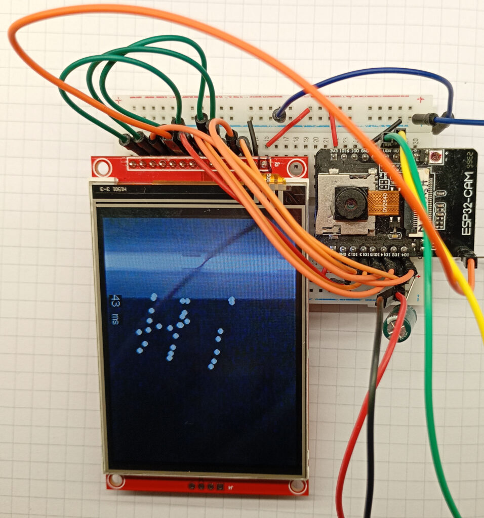

Also pictured in the setup are two flying ground wires, one of them is for grounding GPIO 0 to enter download mode, and the other is for tapping the GND/R pin to reset the ESP32.
After the code has been uploaded to the ESP32CAM, the FTDI adapter can be substituted for a suitable 5V power supply.
I have also added a 100uF capacitor across the power rails – noticed it helps with picture ripple.
Software – User_Setup.h
As always, the code uses the TFT_eSPI.h library by Bodmer, and so the display device settings are calibrated in the User_Setup.h file.
All of the necessary pin definitions, bus speeds and other settings are included in the code included here – simply copy, paste, and save.
This file needs to be correct at time of compiling the code.
#define USER_SETUP_INFO "User_Setup"
#define ILI9341_DRIVER       // Generic driver for common displays
#define TFT_RGB_ORDER TFT_BGR  // Colour order Blue-Green-Red
#define TFT_MISO 33	//can't use onboard LED
#define TFT_MOSI 13
#define TFT_SCLK 14
#define TFT_CS   2  // Chip select control pin
#define TFT_DC    12  // Data Command control pin
#define TFT_RST   15  // Reset pin (could connect to RST pin)
#define TOUCH_CS 4     // Chip select pin (T_CS) of touch screen
#define LOAD_GLCD   // Font 1.
#define LOAD_FONT2  // Font 2.
#define LOAD_FONT4  // Font 4.
#define LOAD_FONT6  // Font 6. only 1234567890:-.apm
#define LOAD_FONT7  // Font 7. only 1234567890:-.
#define LOAD_FONT8  // Font 8. only 1234567890:-.
//#define LOAD_FONT8N // Font 8.
#define LOAD_GFXFF  // FreeFonts.
#define SMOOTH_FONT
#define SPI_FREQUENCY  40000000
#define SPI_READ_FREQUENCY  20000000
#define SPI_TOUCH_FREQUENCY  2500000
#define USE_HSPI_PORT
#define SUPPORT_TRANSACTIONS
Software – Main Sketch
Below is the code for the sketch shown in the initial video. The program allows the user to place a small white circle on the display corresponding to the location of the screen tap.
The sketch is a simple proof-of-concept and is limited to 100 dots with recycle/reuse/delete feature. A device restart is needed to restart the circle count from zero. .
#include "esp_camera.h"
#include <TFT_eSPI.h> // Hardware-specific library
#include <SPI.h>

#define CAMERA_MODEL_AI_THINKER
#define PWDN_GPIO_NUM     32
#define RESET_GPIO_NUM    -1
#define XCLK_GPIO_NUM      0
#define SIOD_GPIO_NUM     26
#define SIOC_GPIO_NUM     27
#define Y9_GPIO_NUM       35
#define Y8_GPIO_NUM       34
#define Y7_GPIO_NUM       39
#define Y6_GPIO_NUM       36
#define Y5_GPIO_NUM       21
#define Y4_GPIO_NUM       19
#define Y3_GPIO_NUM       18
#define Y2_GPIO_NUM        5
#define VSYNC_GPIO_NUM    25
#define HREF_GPIO_NUM     23
#define PCLK_GPIO_NUM     22

TaskHandle_t Task1;

TFT_eSPI tft = TFT_eSPI();       // Invoke custom library
TFT_eSprite spr = TFT_eSprite(&tft);
camera_config_t config;

uint16_t *scr;
long initalTime = 0;
long frameTime = 1;
volatile bool screenRefreshFlag = true;
int canvasX[100];
int canvasY[100];
int canvasCount = 0;
uint16_t t_x = 0;
uint16_t t_y = 0;
Libraries, Definitions, Constructors and Global Variables
The camera pins are defined in this section – if you’re using a different development board then you’ll need to adjust these accordingly.
This sketch uses both cores of the ESP32-S, so a task handler is setup to run the camera on core 0.
If you want to be able to display more than more than 100 dots on the display then increase the number of elements of the canvasX and canvasY arrays.
void setup() {
  Serial.begin(115200);
  tft.init();
  tft.setRotation(3);
  tft.fillScreen(TFT_BLACK);
  tft.setTextColor(TFT_BLACK, TFT_WHITE);
  scr = (uint16_t*)spr.createSprite(320, 240);
  tft.drawString("Loading...", 105, 105, 2);

  for (int initP = 0; initP < 100; initP++){
    canvasX[initP] = -1;
    canvasY[initP] = -1;
  }

  xTaskCreatePinnedToCore(
    Task1code,   // Task function.
    "Task1",     // name of task.
    100000,      // Stack size of task
    NULL,        // parameter of the task
    1,           // priority of the task
    &Task1,      // Task handle to keep track of created task
    0);          // pin task to core 0
  delay(1000);
}
The Setup ( )
This section initialises the display and shows a “Loading…” message on the display for a second.
The code also initialises the X and Y positions of the dots to the co-ordinate of -1,-1. So they exist just off screen.
Finally the task that will handle the camera is configured.
void loop() {
  //refresh display if there is a new image from the camera
  if (screenRefreshFlag) {
    initalTime = millis();
    if (tft.getTouchRawZ() > 600) {
      tft.getTouchRaw(&t_x, &t_y);
      Serial.print(t_x);  Serial.print(", "); Serial.println(t_y);
      int xTouchPixel = map(t_y, 300, 3775, 0, 320);
      int yTouchPixel = map(t_x, 325, 3800, 0, 240);
      if (canvasCount < 100) {
        canvasX[canvasCount] = xTouchPixel;
        canvasY[canvasCount] = yTouchPixel;
        canvasCount++;
      }
    }
    spr.drawString(String(frameTime), 100, 220, 2); //frame time in ms
    spr.drawString("ms", 125, 220, 2);
    //draw circules on to the sprite
    for (int p = 0; p < canvasCount; p++) {
      spr.fillCircle(canvasX[p], canvasY[p], 3, TFT_WHITE);
    }
    spr.pushSprite(0, 0);
    screenRefreshFlag = false;
    frameTime = millis() - initalTime;
  }
}
The Loop ( )
The main loop runs in core 1 and uses an if( ) statement to determine when the camera has captured a new frame on core 0
When the camera flag raised, the touch sensor is polled to see if a press has been registered.
If so, then the raw values from the touch sensor are mapped to their relevant pixel values and saved to the array.
A for( ) loop handles the rendering of the dots by drawing them over the camera frame sprite.
void Task1code( void * pvParameters ) {
  //core0 setup
  config.ledc_channel = LEDC_CHANNEL_0;
  config.ledc_timer = LEDC_TIMER_0;
  config.pin_d0 = Y2_GPIO_NUM;
  config.pin_d1 = Y3_GPIO_NUM;
  config.pin_d2 = Y4_GPIO_NUM;
  config.pin_d3 = Y5_GPIO_NUM;
  config.pin_d4 = Y6_GPIO_NUM;
  config.pin_d5 = Y7_GPIO_NUM;
  config.pin_d6 = Y8_GPIO_NUM;
  config.pin_d7 = Y9_GPIO_NUM;
  config.pin_xclk = XCLK_GPIO_NUM;
  config.pin_pclk = PCLK_GPIO_NUM;
  config.pin_vsync = VSYNC_GPIO_NUM;
  config.pin_href = HREF_GPIO_NUM;
  config.pin_sscb_sda = SIOD_GPIO_NUM;
  config.pin_sscb_scl = SIOC_GPIO_NUM;
  config.pin_pwdn = PWDN_GPIO_NUM;
  config.pin_reset = RESET_GPIO_NUM;
  config.xclk_freq_hz = 20000000;
  config.frame_size = FRAMESIZE_QVGA;
  config.pixel_format = PIXFORMAT_RGB565;
  config.grab_mode = CAMERA_GRAB_LATEST;
  config.fb_location = CAMERA_FB_IN_PSRAM;
  config.jpeg_quality = 12;
  config.fb_count = 2;    //need more than 1 for latest grab

  esp_err_t err = esp_camera_init(&config);
  sensor_t * s = esp_camera_sensor_get();
  s->set_brightness(s, 0);     // -2 to 2
  s->set_contrast(s, 0);       // -2 to 2
  s->set_saturation(s, 0);     // -2 to 2
  s->set_special_effect(s, 0); // 0 to 6
  s->set_whitebal(s, 1);       // 0 = disable , 1 = enable
  s->set_awb_gain(s, 1);       // 0 = disable , 1 = enable
  s->set_wb_mode(s, 0);        // 0 to 4
  s->set_exposure_ctrl(s, 1);  // 0 = disable , 1 = enable
  s->set_aec2(s, 0);           // 0 = disable , 1 = enable
  s->set_ae_level(s, 0);       // -2 to 2
  s->set_aec_value(s, 300);    // 0 to 1200
  s->set_gain_ctrl(s, 1);      // 0 = disable , 1 = enable
  s->set_agc_gain(s, 0);       // 0 to 30
  s->set_gainceiling(s, (gainceiling_t)0);  // 0 to 6
  s->set_bpc(s, 0);            // 0 = disable , 1 = enable
  s->set_wpc(s, 1);            // 0 = disable , 1 = enable
  s->set_raw_gma(s, 1);        // 0 = disable , 1 = enable
  s->set_lenc(s, 1);           // 0 = disable , 1 = enable
  s->set_hmirror(s, 0);        // 0 = disable , 1 = enable
  s->set_vflip(s, 0);          // 0 = disable , 1 = enable
  s->set_dcw(s, 1);            // 0 = disable , 1 = enable
  s->set_colorbar(s, 0);       // 0 = disable , 1 = enable

  //core0 loop
  for (;;) {
    //take picture
    camera_fb_t  * fb = NULL;
    fb = esp_camera_fb_get();
    //transfer frame buffer data to pointer
    for (size_t i = 0; i < 76800; i++) {    //320x240px = 76800
      byte first_byte = fb->buf[i * 2];
      byte second_byte = fb->buf[i * 2 + 1];
      scr[i] = (second_byte << 8) + first_byte;
    }
    screenRefreshFlag = true;
    esp_camera_fb_return(fb); //return frame buf
  }
}
Core 0 – Camera
The important settings to check with this setup are the frame size: QVGA is conveniently the same resolution as the display 320×240.
The pixel format needs to be RBG565 which also conveniently the same format as the display.
The frame buffer location needs to be to PSRAM as there is not enough DRAM to handle a full 24bit image.
As the display is limited to an SPI frequency of 40MHz, the grab mode can be either CAMERA_GRAB_LATEST or CAMERA_GRAB_WHEN_EMPTY. If you use the latter then you can reduce the fb_count to 1.
I’ve not played with the actual sensor settings, so I’m unsure what effects these achieve.
Conclusion
So, to answer the comment from reddit: Yes, with some modification, it is possible to create a GUI with an ESP32CAM and ILI9341 TFT display – hopefully this write-up helps.
I’m always surprised when things like this actually work, especially due to the fiddly nature of the soldering required without a microscope. I’m not going to lie: ‘wins’ like this are always a positive boost to the mental health.
However, in the interests of honesty and openness, this project wasn’t all smooth sailing and involved a number of dead-ends. For example, I tried to use GPIO 16 as the MISO line. But without the PSRAM you’re left with an insufficient amount of internal DRAM, so the serial monitor just fires out panic messages.
I also tried to have the dots on a separate 1-bit sprite, but this halved the frame rate while also creating a horrible flashing effect on the display as it alternated between the camera image and a black screen with white dots.
The build wasn’t much better – I couldn’t desolder the onboard LED very well, so ended up destroying it with snips and then cleaning the solder pads. I’ve also lost one of the resistors which was removed – no chance of finding it again!
In total, it took about 8-10 hours of solid building, coding and testing, not including the additional hours needed to write this webpage and create the associated media. All-in-all, this was time well invested, and I hope it helps someone in the future.
Finally, does this class as augmented reality run locally on an ESP32-CAM? 😉
Page created: 06/09/2025
Last updated: 06/09/2025