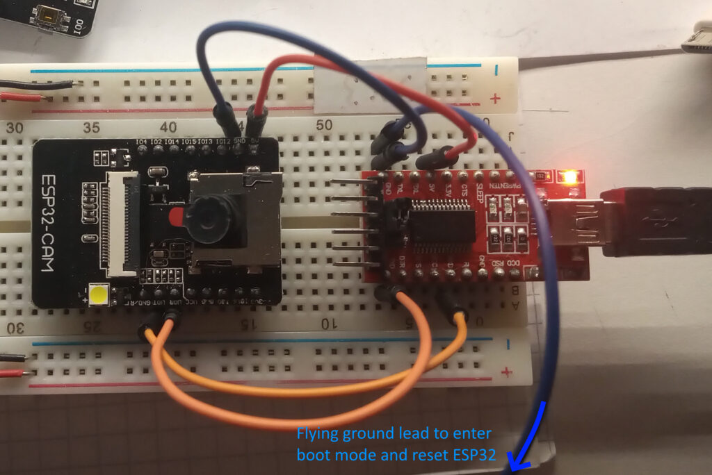
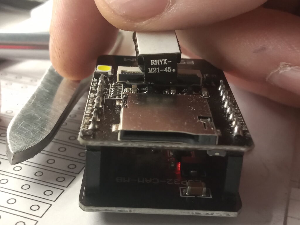
Quick setup to get the AI-Thinker ESP32CAM with the RHYX-M21-45 sensor to display the ubiquitous web camera server. For this demonstration I’ve use the FTDI adapter to program the ESP32CAM.
The RHYX-M21-45 sensor is a 2MP sensor and according to this site it’s also known as a GC2415. The RHYX-M21-45 differs from the standard OV2640 2MP sensor in that it doesn’t have an onboard jpeg encoder, so you can only get RGB565, YCbCr422 and Raw Bayer outputs.
Due to the fact that the sensor doesn’t have a jpeg encoder, the frame size is limited because of frame buffer size. As such there are some tweaks needed to the code. Below is the code required – this is a trimmed down version of the normal web camera server example.
#include "esp_camera.h"
#include <WiFi.h>

#define CAMERA_MODEL_AI_THINKER // Has PSRAM

#include "camera_pins.h"

// ===========================
// Enter your WiFi credentials
// ===========================
const char* ssid = "********";
const char* password = "********";

void startCameraServer();

void setup() {
  Serial.begin(115200);
  Serial.setDebugOutput(true);
  Serial.println();

  camera_config_t config;
  config.ledc_channel = LEDC_CHANNEL_0;
  config.ledc_timer = LEDC_TIMER_0;
  config.pin_d0 = Y2_GPIO_NUM;
  config.pin_d1 = Y3_GPIO_NUM;
  config.pin_d2 = Y4_GPIO_NUM;
  config.pin_d3 = Y5_GPIO_NUM;
  config.pin_d4 = Y6_GPIO_NUM;
  config.pin_d5 = Y7_GPIO_NUM;
  config.pin_d6 = Y8_GPIO_NUM;
  config.pin_d7 = Y9_GPIO_NUM;
  config.pin_xclk = XCLK_GPIO_NUM;
  config.pin_pclk = PCLK_GPIO_NUM;
  config.pin_vsync = VSYNC_GPIO_NUM;
  config.pin_href = HREF_GPIO_NUM;
  config.pin_sscb_sda = SIOD_GPIO_NUM;
  config.pin_sscb_scl = SIOC_GPIO_NUM;
  config.pin_pwdn = PWDN_GPIO_NUM;
  config.pin_reset = RESET_GPIO_NUM;
  config.xclk_freq_hz = 20000000;
  config.frame_size = FRAMESIZE_240X240;
  config.pixel_format = PIXFORMAT_RGB565; // for face detection/recognition
  config.grab_mode = CAMERA_GRAB_WHEN_EMPTY;
  config.fb_location = CAMERA_FB_IN_PSRAM;
  config.fb_count = 2;

  // camera init
  esp_err_t err = esp_camera_init(&config);
  if (err != ESP_OK) {
    Serial.printf("Camera init failed with error 0x%x", err);
    return;
  }

  sensor_t * s = esp_camera_sensor_get();

  WiFi.begin(ssid, password);
  WiFi.setSleep(false);

  while (WiFi.status() != WL_CONNECTED) {
    delay(500);
    Serial.print(".");
  }
  Serial.println("");
  Serial.println("WiFi connected");
  startCameraServer();

  Serial.print("Camera Ready! Use 'http://");
  Serial.print(WiFi.localIP());
  Serial.println("' to connect");
}

void loop() {
  // Do nothing. Everything is done in another task by the web server
  delay(10000);
}
Please note that you’ll need to change your WiFi credentials to your specific network. As it is a local server, you have to use the same network that your computer is using.
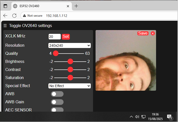
The main changes to the code are to set the pixel format to RBG565 and the frame size to 240×240 pixels.
Connect a ground lead to GPIO 0, tap the reset pin and upload the code.
Once done, remove the ground lead from GPIO 0, open up the serial monitor and reset the ESP32. The microcontroller will then attempt to connect to WiFi and then display a local IP address which is displaying the web camera server.
All being well, enter the IP address to your internet browser, ensure that the 240×240 frame size is set and hit “start stream” at the bottom of the page.
Page created: 15/08/2025
Last updated: 15/08/2025