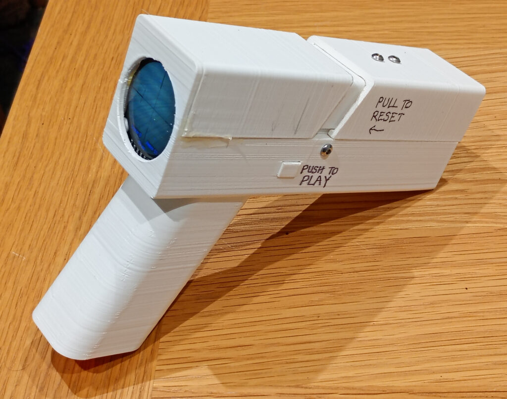
No APIs, no cloud services, no LLMs, no training models, just straight up home-brew computer vision running locally on an ESP32 microcontroller, manifested as a real-time augmented reality target shooting game.
The rules of the game area simple: you have 10 shots to shoot at targets which pop up from your surroundings. The shots are scored, recorded and the game ends when the player has exhausted all of their ‘ammo’. There is no time limit aside from that set by the battery life.
The game utilises your surroundings to provide potential spawning points from where a target may pop up from, all while providing a real time video feed to a GC9A01 circular TFT display.
After the 10 shots, you can view your accuracy on the target and see your score, before hitting reset for more. In this instance, no allowance has been made for cross-winds, gravity or strange trajectories, so the shot position is always deemed as being dead centre.
This page is a write up about a long-term project which was borne from a miscommunication with my wife, and includes all of the pertinent code and schematics used for you to be able to create your own version. I’ve also written about the computer vision techniques used to hopefully make more sense of the code.
While I’m finished with this project (for the moment), that is not to say the project is finished. For a start, the 3D printed model could be improved upon and code is ripe for optimisation.
Preface
This project has taken over a year and a half to complete, partly due to other projects taking precedence, but also because there has been a significant amount of research, testing and implementation required along with various side quests and dead-ends.
To give an idea of the leg-work required to get to this stage, here is a list of prior posts, pages & projects which have all contributed in some way. This list doesn’t even include the misadventures and experiments that didn’t even warrant documenting.
- 13th June 2024
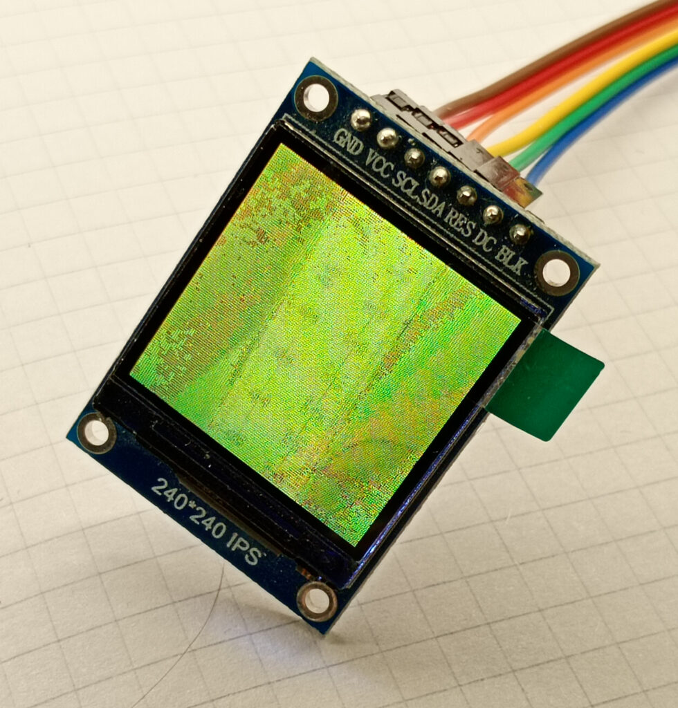
The first initial hardware tests to see if it’s possible to display a live video feed from the ESP32-CAM on to a circular GC9A01 display, and if so, then to determine the frame rates that might be possible. - 8th September 2024
As that the AI-Thinker ESP32-CAM has a dual core Xtensa LX6 CPU, this experiment was about shifting the camera and display code on to core_0 to free up the other core for the computer vision bollocks. - 3rd October 2024
To test kernel convolutions, pixel data is needed. So, this used the code from the previous experiments to export a data stream via the serial monitor. The data was outputted as a .csv format for easy import to Excel. - 3rd January 2025
During the Christmas / New Year break of 2024/25, an initial idea for motion tracking was tested based on the analysis done in Excel. While the results were underwhelming, the gain in experience and confidence was invaluable. - 5th March 2025
Curiosity then led to a side quest to get an SH1106 OLED display showing the video feed. While ultimately pointless, the monochrome display meant that this was the first foray into colour conversion utilising a basic mid-point threshold. - 15th June 2025
After the Christmas break, there was no progress for 6 months due to working solidly on another project for college. However, within a week of submitting the college project, initial tests were done on real-time edge detection. These experiments were even worthy of a Hackster.io article! - 22nd June 2025
As the output of the edge detection was either simple yes/no, curiosity decided to see if it was possible to ‘port’ the code across to an ST7920 LCD graphic display. While technically pointless, it did give further experience with pixel handling. - 26th July 2025
Addressing the elephant in the room: frame rate. At this moment in time, the edge detection was running at less than 4 FPS. So to get around this issue, work on Plan B began: Take a high resolution static image and then control a small window with a joystick. Had to use an ST7789 display for this one to free up additional pins for the joystick. Ironically, the results were just as slow, so the experiment fizzled into obscurity. - 4th September 2025 [reddit link]
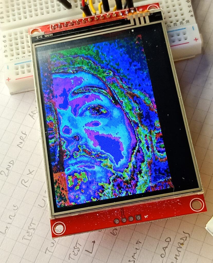
At this point, the project felt lost. But from the one gem the previous experiment was that the OV2640 sensor could produce a QVGA(320×240) frame as fast as a 240x240px frame. As the ILI9341 display uses the same QVGA resolution, I just couldn’t help myself. At this point the display turned out to be the bottleneck! - 6th September 2025
Building on the momentum of the success with the ILI9341, the AI-Thinker ESP32-CAM was physically modified to express two additional GPIO pins necessary to enable the touch screen interface to work. Now you can draw on your pupils: completely pointless, but this experiment technically meets the definition of augmented reality. - 21st November 2025
At a similar time to all of this, I was also utilising nRF24L01 modules for another project. Given that the displays and nRF24 modules all work on the SPI bus, I decided to see if it was possible to transmit the video wirelessly to another ESP32. This opened a rabbit warren of radio testing. - 5th January 2026
Side quests are important. While stalling on the gap between edge detection and edge tracking, this experiment in to motion detection using the difference between consecutive frames helped to plant some idea-seeds.

Theory of Operation
The code is pretty much a single monolithic lump running inside the loop( ) function. So, instead of just dumping this absolute mess, below is my attempt to explain the various techniques used to cajole the limited hardware to perceive it’s surroundings in a timely manner.
However, if you don’t care for this waffle then feel free to skip straight to meat and potatoes below.
Greyscale Conversion
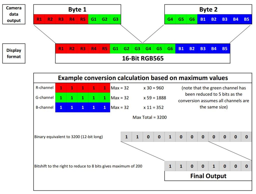
The display demands a byte-swapped 16-bit RGB565 format, and the camera will export a 16-bit RGB565 format, so that makes sense. But the three colour channels need to be combined to a single luminance value for the simplicity of future calculations.
The conversion algorithm used here based on the BT.470 system which determines the luma (luminance) as:
Y' = (0.299 * R) + (0.587 * G) + (0.114 * B)
To avoid hardware-intense floating point arithmetic, the constants have been rounded to two decimal points and multiplied by 100 to give the bastardised formula as:
Y' = (30 * R) + (59 * G) + (11 * B)
As the above would give a theoretical maximum of 3200, this is then bit shifted 4 places to the right (i.e. divided by 16). This does mean there is a a loss of fidelity, as a the value range decreases from 0-255 to 0-200.
Edge Detection
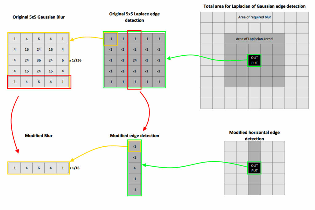
From previous edge detection experiments, the optimal configuration was applying a 5×5 Laplace kernel over a 5×5 Gaussian blur, but this process only yielded a refresh rate of 3-4FPS.
Due to the size of the Gaussian and Laplacian kernels, a total of 650 calculations are required for a single pixel output. Multiply this over 53,824 pixels required for a single frame, and it’s easy to see why the humble 240Mhz processor is taking a little while.
To combat this computationally heavy method, and also filter out any non-horizontal edges, the two kernels were bastardised to a single dimension array and convoluted perpendicularly to their direction, thus taking the calculation total down to 30.
Analysis of different versions of kernel were tested using Excel, and outputted as an X-Y scatter plot graph to assess the necessary thresholds, and various different kernels were tested.
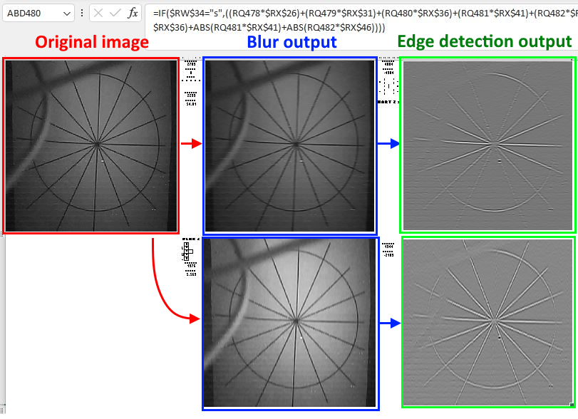
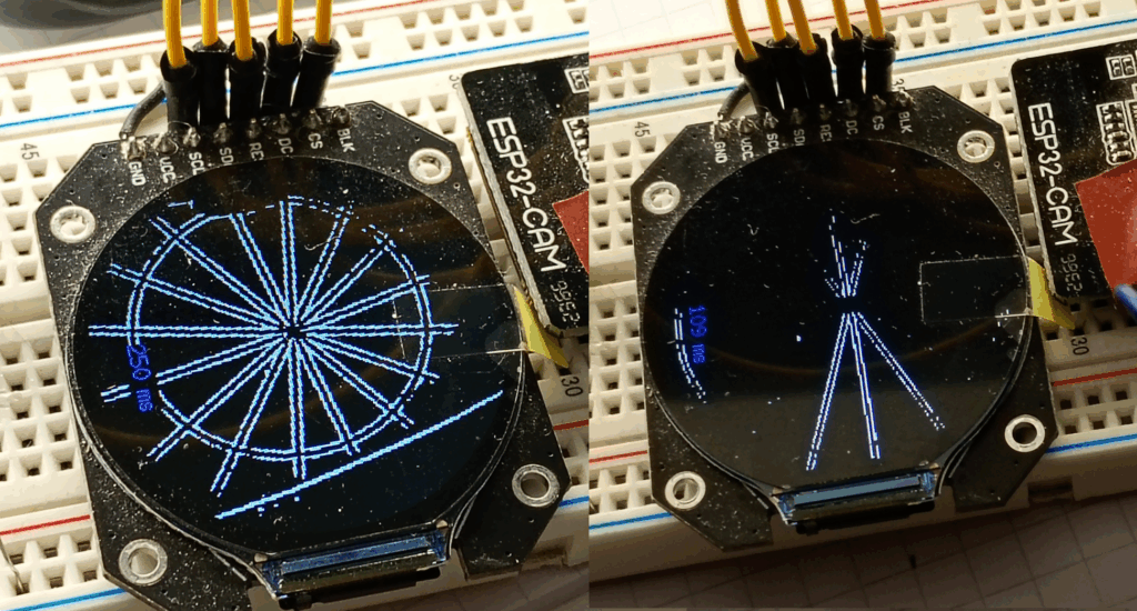
Right: edge detection using the modified kernels. (109ms frame time)
Scan Strategy
Previous experiments with edge detection have convoluted the kernel from left to right to complete an entire row, before moving down to the next row and repeating for the whole frame; not dissimilar to the pattern traced out by the electron beam in CRT displays.
Making a few broad assumptions and some sweeping statements statements, it’s possible to reduce the scan area and make the process more efficient.
To start: as the target is 40 pixels high, therefore if a line is detected in the first 39 rows then the top of the target would be missing. As such, the top 39 rows of pixels are cut off the scan area, reducing the scan area by 9,440 pixels.
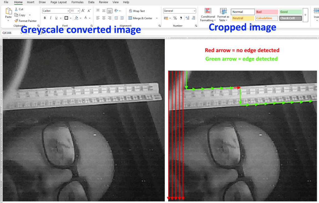
Given that the game focusses on horizontal lines, the orientation of the scan lines is rotated by 90 degrees, so that the convolution goes from top to bottom, one column at a time.
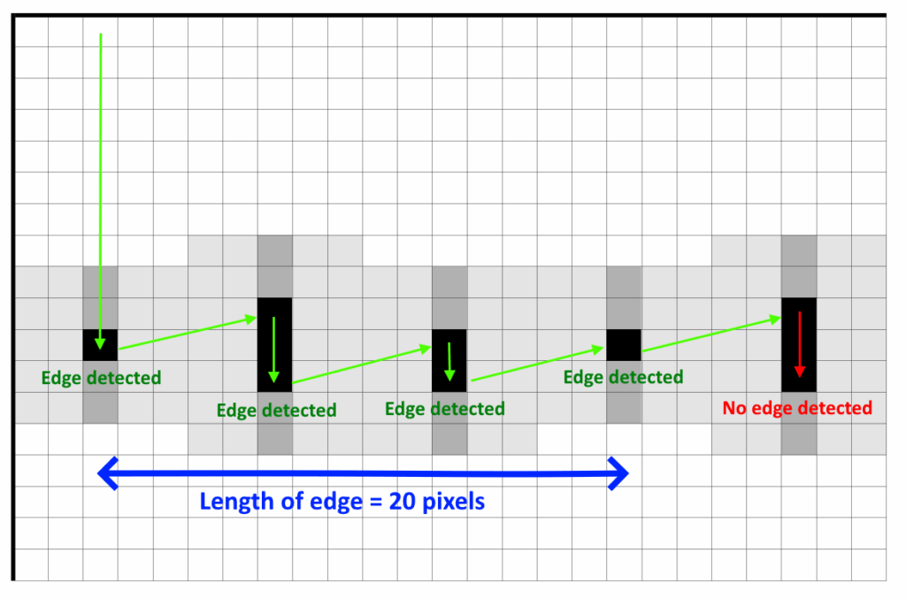
Continuing with the broad generalisations: it makes no sense to continue the downward scan if an edge IS detected. So, when an edge value is detected above the threshold value, the scan position skips ahead five columns at the same height, and analyses that pixel, plus the one above and below to see if the edge continues.
As there can be a variation of +/-1 pixel in height for every 5 pixels across – this allows for detection of lines that deviate +/- 11.3degrees from normal, so for a full 240 pixel width screen, there could be a total change in height of 48 pixels: so the initial scan area is cropped by another 8 pixels.
By adopting this strategy, rather than processing whole frames at a time, it is possible to utilise the internal SRAM of the ESP32 chip, rather than rely on external PSRAM. One source[reddit] speculates that the SRAM throughput is 24 times greater than the PSRAM, thus greatly increasing the frame rates.
Another positive outcome of skipping columns, means that the frame is processed quicker – achieving a consistent 12.5FPS. But why was the frame rate ‘consistent’?
This lead down a complete rabbit warren of testing and experimentation, because surely if there is a continuous horizontal edge across the entire frame of view, then there would only be 48 sets of calculations, rather than having to scan 218 individual columns if there are no edges?
Turns out that the fb_get() function, which obtains the sensor data varies in duration from about 17ms to 32ms. The amount of variation is always inverse to the period of time taken to process the frame, so that the sum of both parts is always 52ms.
| Process | Duration if LONG edge detected | Duration if NO edge detected |
|---|---|---|
| fb_get( ) | 32 ms | 17 ms |
| Transfer to PSRAM | 20 ms | 19 ms |
| “Computer vision” | 2 ms | 18 ms |
| Total time | 52 ms | 52 ms |
Line Classification and Tracking
Now with an efficient way of detecting horizontal edges, it’s just a matter of getting a target to pop up from that edge. Starting with some generalised statements about the behaviour of the target can assist in creating a suitable algorithm:
- There should only be one target displayed on the screen at once.
- The target should also remain in the same position relative to the surroundings.
To determine where the target should pop up from, the detected edges need to be classified for suitability. The easiest way is to measure the starting co-ordinates and end co-ordinates of the edge, and use these to calculate the length.
Having data about the length of the edge, allows them to be sorted: edges that are below the width of the target can be discarded as they are unsuitable. In addition to this, each length is checked against any previous edges in the frame and only the longest edge is processed further.
Using the initial and final co-ordinates of the longest edge, the centre point can be calculated, and this forms the point of interest (PoI) that is committed to memory and subsequently compared against in the following frame.
The comparison between the PoI’s of subsequent frames is calculated from the absolute differences of the X&Y co-ordinates to give a difference of distance. Should this difference be within a threshold, then a counter is incremented to measure persistence of an edge.
Only when an edge and it’s relative point of interest have persisted long enough, is a target then displayed. The centre point of bottom of the target is located at the point of interest, with the persistence counter providing a height for the target to pop up at.
The centre points of the cross hairs in the game have fixed co-ordinates (120, 120). So, when the trigger button is pressed, the co-ordinates from the most recent point of interest are compared to the centre point co-ordinates to calculate the distance to the centre of the target.
Electrical
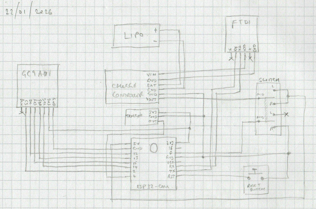
Schematic
Below is the electrical schematic for the circuit.
Bill of materials
I have no affiliations to the links provided – they will probably 404 over time.
| Quantity | Description | Link |
|---|---|---|
| 1 | AI-Thinker ESP32-CAM module, with OV2640 2MP sensor. (The RHYX-M21-45 sensor should also work) | FT232 FT232RL FTDI USB 3.3V 5.5V to TTL Serial Adapter Module Type-C | eBay UK |
| 1 | USB FT232 FTDI TTL serial adapter – 5V. (No preference on USB-C, or USB-B Mini) | ESP32-CAM WIFI Bluetooth Board & OV2640 Camera Module ESP 32 Cam | eBay UK |
| 1 | GC9A01 1.28inch round TFT display. | Round TFT 1.28″ inch LCD Display RGB 3.3V 240*240 GC9A01 SPI for Arduino Pi | eBay UK |
| 1 | 5V Output lithium charge / discharge controller. | https://www.ebay.co.uk/itm/267248509843 |
| 1 | Double pole, double throw, 3-position on-off-on slide switch. The size of the toggle will need to suit the mechanism. | https://www.ebay.co.uk/itm/255812067310 (closest match, original supplier non-existent) |
| 2 | 6x6mm momentary tactile push button (NO) through-hole. The reset switch is 17mm high The trigger switch is 5mm high | 10 x Tactile Tact Switch Momentary Switch 6mmx6mm Push Button Switch 12V 4PIN UK | eBay UK (closest match, original supplier non-existent) |
| 1 | 3.7V LiPo battery – 1100mAh – 402863. | 3.7v Batteries Rechargeable LiPo Lithium Polymer Various Size High Quality Cells | eBay UK |
| 1 | 4.7kOhm SMD resistor (1206 size). This is just for a pull-down, so any value up to 10kOhm will suffice. And through hole will work fine | SMD SMT 1206 Chip Resistor 0R – 1M Ohm Range Free P&P | eBay UK |
| Some | Wire of your choosing. I’ve used 22AWG stranded silicone coated wire. The previous version used 22AWG. There is no ‘right’ answer, but consider that space is tight in the enclosure. | |
| Some | Consumables, including but not limited to: Solder, flux, solder wick Heat shrink to suit your wire Female headers (2 rows of 8) Perf board 2.54mm 2pin JST connector (for battery) |
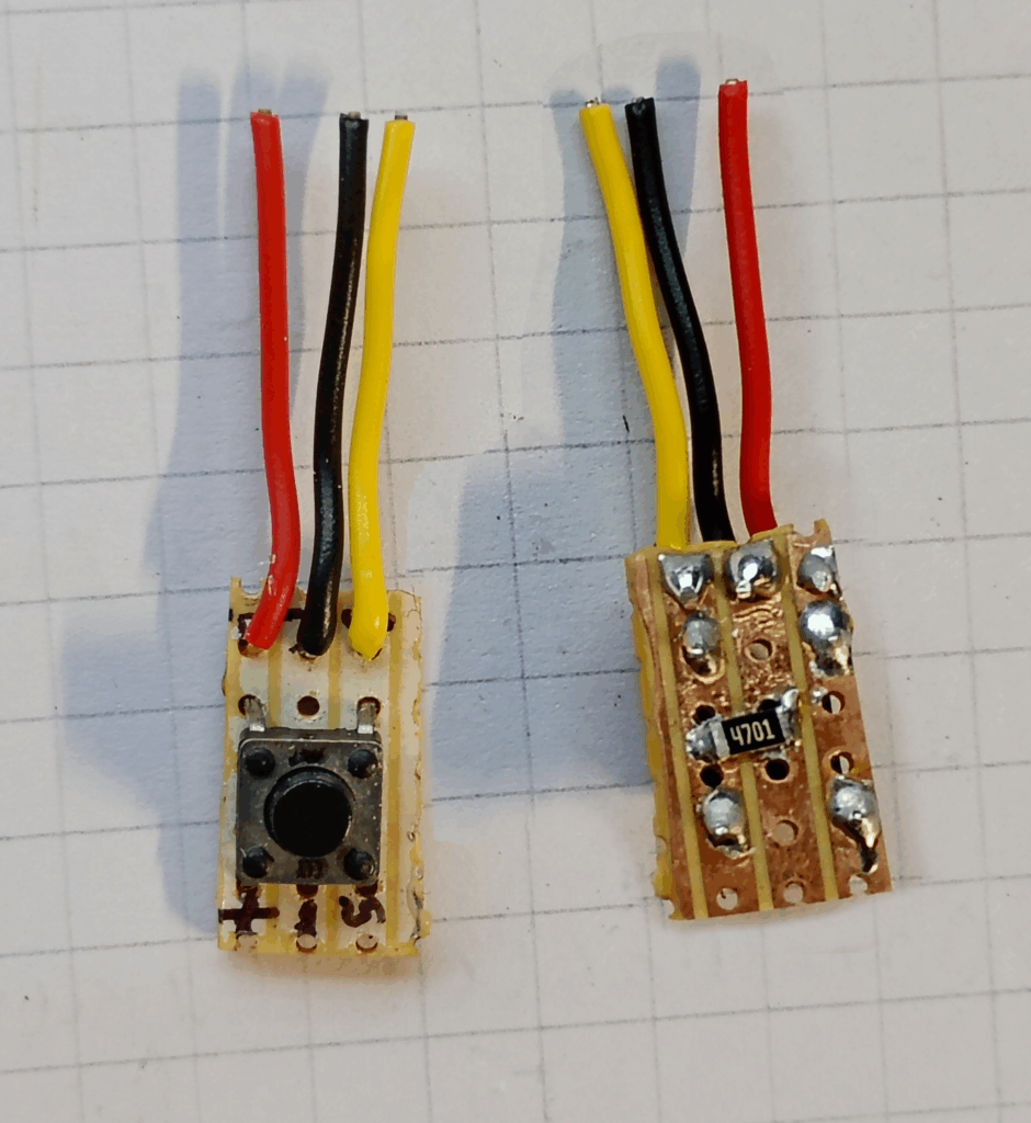
Switch Assemblies
Reset Switch
Trigger Switch
Boot Selector Switch
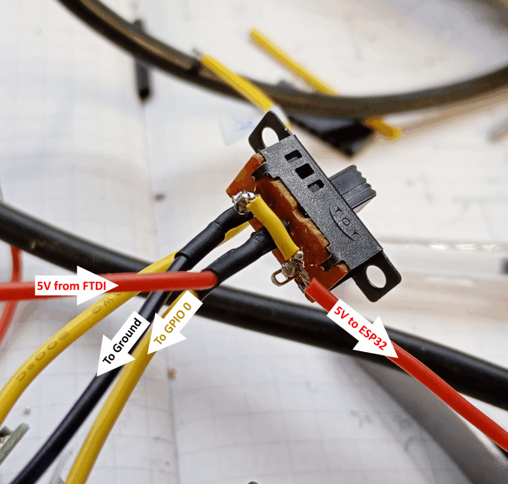
The other row of pins to be connected to ground in the middle, then have one side connected to GPIO 0.
Mechanical
Bill of Materials
| QTY | Description |
|---|---|
| Some | PLA filament (or other type to suit your preference / printer – just note that you’ll need to tolerance the parts). |
| 6 | M3 x 8 button head hex screws |
| 1 | Compression spring, 8mm diameter, 20mm high. (I used the spring from an OG Ender3 print bed) |
| Some | Hot glue Super glue Electrical tape |
| Lots | Patience |
| Tools | Hot glue gun Hex/Allen key (2mm) Needle files & sand paper (60-80 grit) Drill + 3mm multipurpose drill bit Soldering iron / Hot air station JST crimp set (optional) Cross lock tweezers (optional – recommended) |
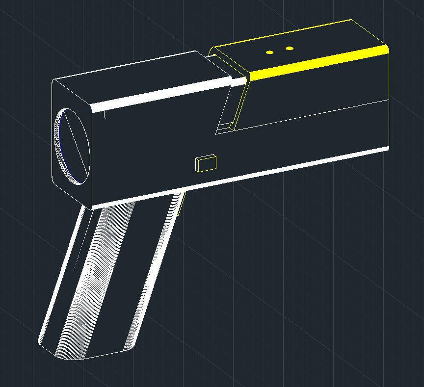
3D Files
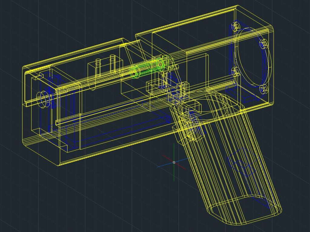
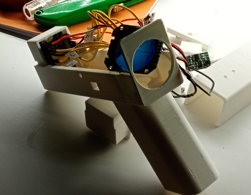
These are the STLs for the model shown above. I’m not a mechanical designer & this design is proof – nearly all the parts will require some sort of fettling. The print settings are for guidance only and may differ on your machine, however, the model has been designed for a 0.4mm FDM nozzle set to a 0.20mm layer height.
| Part | Image | Print settings | Download file |
|---|---|---|---|
| Grip | 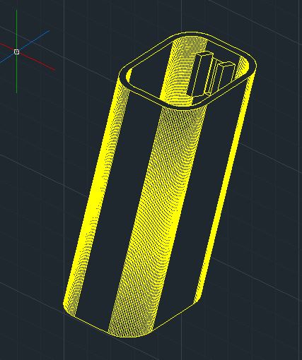 | Orientated as seen, but rotated with switch at the bottom. Supports touching build plate | Grip STL |
| Bottom body | 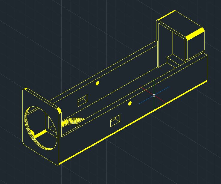 | Orientated as seen. Supports for entire model. | Bottom Case STL |
| Reset slide | 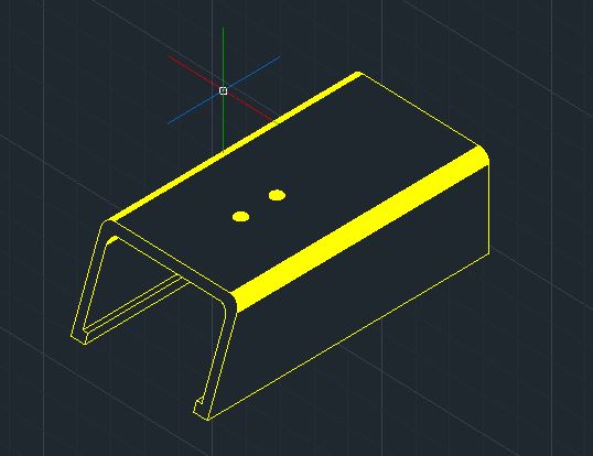 | Orientated upright with front face flat on the bed. No supports. | Reset Slide STL |
| Top case | 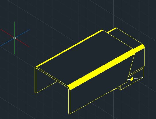 | Orientated upright with busy end flat on the bed. Supports touching build plate. | Top Case STL |
| Trigger button | 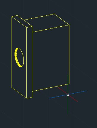 | Orientated so largest face is flat on the bed. No supports. | Trigger Button STL |
| Boot selector slide | 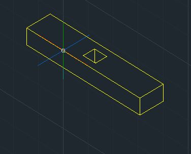 | Orientated as seen. No supports. | Boot Selector STL |
| Reset switch nubbin | 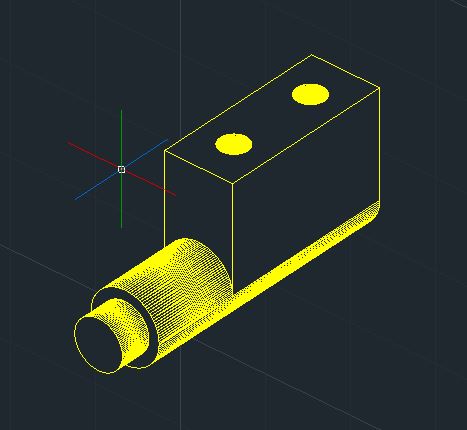 | Orientated upright with large end on the bed. No supports. | Reset Pin STL |
| Reset back strap | 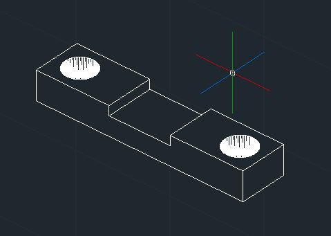 | Orientated as seen. No supports. | Reset Hold Strap STL |
Assembly Instructions
The best order of assembly is the order that works for you. However, this is the order I followed:
- Prototype all of the electrics on a bread board, and check that you can flash the program to the ESP32.
- Solder all of the electrical components together to form a ganglion of wires and components. Test again. I’ve used a set of two 8-pin female headers to interface with the ESP32 – this allows for the rest of the components to be glued in place and push the final connections in. (Extra points for forming a detachable connector to interface the battery)
- Print all the parts and do a dry fit before trying to assemble anything. This will highlight where you need to file and sand the parts to make them fit. Pay attention to the moving parts such as the reset slide, selector switch and trigger.
- Drill out the two holes in the bottom section of the case with an 3mm bit. Also drill out the two holes of the strap that holds the reset switch.
- Align the grip on to the body and temporarily secure in place with self-adhesive tape. Super glue the joint with the lower case and allow to dry.
- Use the hot glue gun to fix the ESP32 in to the front of the case, ensuring that the camera faces out of the hole and that none of the pins are covered with glue. Also try not to cover the voltage regulator – can’t imagine the insulative properties would help.
- (Optional for detachable battery). Tack down the LiPo cell with a tiny touch of hot glue in the corners – avoid transferring heat to the pouch or electronics.
- Place the reset switch in the reset switch hole of the top case part. Fix in place using the fixing strap and a pair of M3 screws – push hard as the screw will self-tap a thread.
- Slip the boot-mode selector switch in to the appropriate position and hold in place with a dab of hot glue. Check that the switch still operates after gluing.
- Feed the FTDI adapter and associated jumble of wires down the grip and adhere the FTDI to the insider with more hot glue. Ensure there is a good mechanical bond to avoid dislodging when inserting/removing the USB cable.
- Place the trigger in to the trigger hole and cover with the trigger switch assembly – check that the switch positively triggers and correctly springs back. Once arranged, immortalise the setting with hot glue. Check operation after glue has set.
- Continuing on with the liberal use of hot glue – affix the display in the correct location. Again, take care not to damage any of the components with excessive heat.
- Feed the boot-mode selector switch through the body, and ensure the wires go under the selector: there is no room above (glaring oversight on my part). Using tweezers was essential to thread the complex weave of needle nosed. The process is fiddly, annoying and compact. You have to mash down the wires, and charge controller, while simultaneously placing the top part of the case on to the lower part, aligning the holes and screwing the two M3 fixings in place.
- If you haven’t connected your battery, then cuss loudly and undo the work completed in the previous step and connect the battery.
- Take the spring and stick it down the spring hole.
- Partially slide the reset slide along the rails of the main body, and offer the reset pin to the underside of the slide. You’ll need tweezers to hold the pin in place while you screw it in using another two M3 screws.
- To finish, carefully garnish the front face with a small piece of self adhesive tape to prevent the reset slide from sliding off.
Software – Graphics
User_Setup.h File
As usual, the program uses the TFT_eSPI library by Bodmer, so the correct User_Setup.h file must be set at the time of compiling the main code. This is based on the GC9A01 display driver for a 240x240pixel colour TFT display.
#define USER_SETUP_INFO "User_Setup"
#define GC9A01_DRIVER
#define TFT_SDA_READ      // This option is for ESP32 ONLY, tested with ST7789 and GC9A01 display only
#define TFT_HEIGHT 240 // GC9A01 240 x 240

#define TFT_MOSI 13 // In some display driver board, it might be written as "SDA" and so on.
#define TFT_SCLK 14
#define TFT_CS   2  // Chip select control pin
#define TFT_DC   12  // Data Command control pin
#define TFT_RST  15  // Reset pin

#define LOAD_GLCD   // Font 1.
#define LOAD_FONT2  // Font 2.
#define LOAD_FONT4  // Font 4.
#define LOAD_GFXFF  // FreeFonts.
#define SMOOTH_FONT

#define SPI_FREQUENCY  40000000
#define SPI_READ_FREQUENCY  20000000
#define USE_HSPI_PORT
#define SUPPORT_TRANSACTIONS
You can increase the SPI_FREQUENCY to 80000000, but there is no discernible difference in performance.
Graphics Files
The cross hairs are drawn with drawLine( ) and fillRect( ) functions, however, the small pop-up target, large final target, and ‘shot blast’ are predefined graphics from a header file.
The links will take you to the code, however you’ll need to copy, paste and save as a .h file with the name given at the top of the page, within the same folder as the main sketch.
I’ve not explained this very clearly. If you get “cannot find xxxx” errors, then it’s due to the file naming.
| Graphic Name | Image | Size | Link to File |
|---|---|---|---|
| Small target | 30×40 pix 12kB | Small target.h | |
| Large target |  | 180×240 pix 412kB | Large target.h |
| Flash bang | 20×20 pix 5 kB | Flash bang.h |
Software – Code
Prepare yourself for the ugliest blob of code you’ve ever seen. As always, I’ll try and explain the nuances and magic numbers along the way. While I have tried to tidy the code, there are likely to be vestigial functions and unused variables throughout as evidence of the experiment’s evolution.
#include "esp_camera.h"
#include <TFT_eSPI.h> // CHECK YOUR User_Setup.h File.
#include <SPI.h>

#include "test_target3040pngH.h"
#include "test_target240b.h"
#include "testBlast.h"

#define CAMERA_MODEL_AI_THINKER
#define PWDN_GPIO_NUM     32
#define RESET_GPIO_NUM    -1
#define XCLK_GPIO_NUM      0
#define SIOD_GPIO_NUM     26
#define SIOC_GPIO_NUM     27
#define Y9_GPIO_NUM       35
#define Y8_GPIO_NUM       34
#define Y7_GPIO_NUM       39
#define Y6_GPIO_NUM       36
#define Y5_GPIO_NUM       21
#define Y4_GPIO_NUM       19
#define Y3_GPIO_NUM       18
#define Y2_GPIO_NUM        5
#define VSYNC_GPIO_NUM    25
#define HREF_GPIO_NUM     23
#define PCLK_GPIO_NUM     22

#define TRIGGER_SWITCH    4

TFT_eSPI tft = TFT_eSPI();
TFT_eSprite spr = TFT_eSprite(&tft);
TFT_eSprite spr_target = TFT_eSprite(&tft);
volatile uint16_t *scr;

camera_config_t config;
camera_fb_t  * fb;

long initalTime = 0;
long frameTime = 0;

//co-ordinate of interest for motion detection
int root_x;
int root_y;

//line & POI co-oridinates and flag and length
int x_0;
int y_0;
int x_1;
int y_1;
int x_c_0;
int y_c_0;
int x_c_1;
int y_c_1;
int POI_count = 0;
int POI_x;
int POI_y;
bool line_detected = false;
bool line_suitable = false;
int line_length;
int longest_length = 0;
int target_height = 0;

//create array of 5 localised blur results
int blur_result[5];
int temp_blur_result[7];

//detection threshold, 0 - 255, 127 = mid point
//changed threshold to 100 as greyscale output is 0-200
const int detection_threshold = 100;
int detection_count = 0;

//constants for the button/trigger
const int x_crosshair = 120;
const int y_crosshair = 120;

//player credentials
int score = 0;
int ammo_count = 10;
int ammo_x[10];
int ammo_y[10];
long last_shot_time = 0;
Libraries, Inclusions and Globals
This includes all of the necessary libraries for the camera and display, as well as the graphics files mentioned previously.
The camera pins are defined, and all the various objects are created for the display, sprite, and camera.
In addition to this, a metric butt-load of global variables and constants are declared, and some are initialised, too!
void setup() {

  psramInit();
  Serial.begin(115200);
  //Serial.println("x, y");

  pinMode(TRIGGER_SWITCH, INPUT);

  config.ledc_channel = LEDC_CHANNEL_0;
  config.ledc_timer = LEDC_TIMER_0;
  config.pin_d0 = Y2_GPIO_NUM;
  config.pin_d1 = Y3_GPIO_NUM;
  config.pin_d2 = Y4_GPIO_NUM;
  config.pin_d3 = Y5_GPIO_NUM;
  config.pin_d4 = Y6_GPIO_NUM;
  config.pin_d5 = Y7_GPIO_NUM;
  config.pin_d6 = Y8_GPIO_NUM;
  config.pin_d7 = Y9_GPIO_NUM;
  config.pin_xclk = XCLK_GPIO_NUM;
  config.pin_pclk = PCLK_GPIO_NUM;
  config.pin_vsync = VSYNC_GPIO_NUM;
  config.pin_href = HREF_GPIO_NUM;
  config.pin_sscb_sda = SIOD_GPIO_NUM;
  config.pin_sscb_scl = SIOC_GPIO_NUM;
  config.pin_pwdn = PWDN_GPIO_NUM;
  config.pin_reset = RESET_GPIO_NUM;
  config.xclk_freq_hz = 20000000;
  config.frame_size = FRAMESIZE_240X240;
  //config.pixel_format = PIXFORMAT_GRAYSCALE;
  config.pixel_format = PIXFORMAT_RGB565;
  config.grab_mode = CAMERA_GRAB_LATEST;
  config.fb_location = CAMERA_FB_IN_PSRAM;
  config.jpeg_quality = 12;
  config.fb_count = 2;

  esp_err_t err = esp_camera_init(&config);

  sensor_t * s = esp_camera_sensor_get();
  s->set_brightness(s, 0);     // -2 to 2
  s->set_contrast(s, 0);       // -2 to 2
  s->set_saturation(s, 0);     // -2 to 2
  s->set_special_effect(s, 0); // 0 to 6
  s->set_whitebal(s, 1);       // 0 = disable , 1 = enable
  s->set_awb_gain(s, 1);       // 0 = disable , 1 = enable
  s->set_wb_mode(s, 0);        // 0 to 4 - i
  s->set_exposure_ctrl(s, 1);  // 0 = disable , 1 = enable
  s->set_aec2(s, 0);           // 0 = disable , 1 = enable
  s->set_ae_level(s, 0);       // -2 to 2
  s->set_aec_value(s, 300);    // 0 to 1200
  s->set_gain_ctrl(s, 1);      // 0 = disable , 1 = enable
  s->set_agc_gain(s, 0);       // 0 to 30
  s->set_gainceiling(s, (gainceiling_t)0);  // 0 to 6
  s->set_bpc(s, 0);            // 0 = disable , 1 = enable
  s->set_wpc(s, 1);            // 0 = disable , 1 = enable
  s->set_raw_gma(s, 1);        // 0 = disable , 1 = enable
  s->set_lenc(s, 1);           // 0 = disable , 1 = enable
  s->set_hmirror(s, 0);        // 0 = disable , 1 = enable
  s->set_vflip(s, 0);          // 0 = disable , 1 = enable
  s->set_dcw(s, 1);            // 0 = disable , 1 = enable
  s->set_colorbar(s, 0);       // 0 = disable , 1 = enable

  tft.init();
  tft.setRotation(2);
  tft.fillScreen(TFT_BLACK);
  tft.setTextColor(TFT_BLACK, TFT_WHITE);

  spr_target.createSprite(30, 40);  //30x40 sprite for target
  scr = (uint16_t*)spr.createSprite(240, 240); //full frame
  //scr = (uint16_t*)spr.createSprite(236, 236); //for 3x3
  //scr = (uint16_t*)spr.createSprite(232, 232);  //for 5x5


  spr.setTextColor(TFT_BLUE, TFT_BLACK);
  tft.setTextColor(TFT_WHITE, TFT_BLACK);
  tft.drawString("Loading...", 105, 105, 2);
  delay(1000);
}
The Setup( )
Fairly typical setup function were the PSRAM, Serial port and display are all initiated. The camera sensor settings are configured, and sprite created.
The final section contains the code for the “loading…” screen – a useful diagnostic to determine if the display is working.
uint16_t convertToGreyscale(int RGB) {

  uint16_t R = (0b1111100000000000 & RGB) >> 11;
  uint16_t G = (0b1111110000000000 & (RGB << 5)) >> 11;
  uint16_t B = (0b1111100000000000 & (RGB << 11)) >> 11;

  uint16_t greyscale = (R * 30 ) + (G * 59) + (B * 11);   //returns theoretical 0-3200
  uint16_t greyscale_small = greyscale >> 4;
  return greyscale_small;

}
Greyscale Converter
This is the only function written outside of the main loop and was surreptitiously stolen from a previous experiment.
The function takes a 16bit RGB value, applies a mask to express the three colour channels, applies the bastardised weightings and returns a 16bit greyscale equivalent value.
void loop() {

  //"Game" code - what happens when button pressed.
  if (digitalRead(TRIGGER_SWITCH)) {
    if ((last_shot_time + 200) < millis()) {    //debounce
      tft.pushImage(110, 110, 20, 20, testBlast, 0xFFFF);
      last_shot_time = millis();
      ammo_count--;

      int aim_x = POI_x - x_crosshair;
      int aim_y = POI_y - (y_crosshair + 13);

      ammo_x[ammo_count] = (x_crosshair - POI_x) + 15;
      ammo_y[ammo_count] = 40 - (POI_y - y_crosshair) - (40 - (target_height * 8));

      int sq_aim = (aim_x * aim_x) + (aim_y * aim_y);
      int aim_h = sqrt(sq_aim);

      if (ammo_x[ammo_count] < 30) {
        if (ammo_y[ammo_count] < 40) {
          POI_count = 0;           //reset point of interest
          POI_x = 0;
          POI_y = 0;
          target_height = 0;      //reset target height

          if (aim_h < 12) {
            score += (12 - aim_h);   //12 being perfect
          }
        }
      }


      Serial.print(ammo_x[ammo_count]); Serial.print(", "); Serial.print(ammo_y[ammo_count]); Serial.print(" = ");
      Serial.println(aim_h);

      if (ammo_count < 1) {
        //out of ammo
        delay(1000);
        tft.pushImage(30, 0, 180, 240, test_target240b);
        for (int ammo_display = 0; ammo_display < 10; ammo_display++) {
          tft.fillCircle((ammo_x[ammo_display] * 6) + 30, ammo_y[ammo_display] * 6, 4, TFT_GREEN);
        }
        delay(5000);
        tft.drawString("Press trigger for score", 45, 200, 2);
        while (digitalRead(TRIGGER_SWITCH) == 0);   //hold until trigger press
        tft.fillScreen(TFT_BLACK);
        tft.drawString("Game Over", 60, 80, 4);
        tft.drawString("Total score:", 63, 120, 2);
        tft.drawNumber(score, 163, 120, 2);
        tft.drawString("Press trigger to restart", 50, 160, 2);
        delay(500);
        while (digitalRead(TRIGGER_SWITCH) == 0);   //hold until trigger press
        ammo_count = 10;
        score = 0;
        delay(500);
      }
    }
  }
Loop( ) Part 1: Game Controls
As soon as the loop starts, it polls the trigger switch to determine if the trigger has been pressed; should the answer be no, then nothing is done and the code progresses.
However, if the trigger is pressed (and not pressed sooner than 200ms from the previous press) then the blast image is pushed to the sprite, while also decreasing the “ammo” count.
The x & y offsets are calculated by subtracting the crosshair constants from the current point of interest variables and saved to an array for later display. The hypotenuse distance is calculated using good-old Pythagoras’ theorem and deducted from the magic number 12 and the difference is saved to the score.
Twelve is the magic number because it is the maximum radius of the target. Anything greater is classed as a miss, and anything less is appended to the score total. This gives a maximum score of 120.
This section of code also handles when the player has expended all of their shots, and will show the final target with suitably mapped shots, before allowing them to restart the game.
  initalTime = millis();
  detection_count = 0;
  longest_length = 0;

  //PS ram allocaions
  int *greyscale_frame = (int *) ps_malloc(57600 * sizeof(int));


  //take photo
  camera_fb_t  * fb = NULL;
  fb = esp_camera_fb_get();

  //transfer camera frame to sprite pointer
  //and convert to greyscale in PSRAM
  for (int i = 0; i < 57600; i++) {
    byte sub_pix_a = fb->buf[i * 2];
    byte sub_pix_b = fb->buf[i * 2 + 1];
    scr[i] = (sub_pix_b << 8) + sub_pix_a;    //swap byte order for display
    //frame_buffer[i] = (sub_pix_a << 8 ) + sub_pix_b;
    int temp_colour_pixel = (sub_pix_a << 8 ) + sub_pix_b;
    greyscale_frame[i] = convertToGreyscale(temp_colour_pixel);
  }

  esp_camera_fb_return(fb);

  int blur_subtotal;
  int blur_subtotal_location;
  int detection_value;
Loop Part 2: Prepare Your Frame for Analysis
As the title alludes; this section of code resets all of the necessary variables back to zero and allocates the necessary space in the PSRAM for a new greyscale frame.
The camera then takes a photo, which is set to the to the display sprite as a colour image while also converting to greyscale and saved to PSRAM.
  //setup 218 columns for initial detection area = omit first 2 and final 20 columns
  for (int scan_area_x = 2; scan_area_x < 220; scan_area_x++) {

    //calculate initial blur areas of top 5 rows - always start at the top of the column
    for (int blur_count = 0; blur_count < 5; blur_count++) {
      blur_subtotal = 0;
      blur_subtotal_location = ((blur_count * 240) + scan_area_x);

      blur_subtotal += greyscale_frame[blur_subtotal_location - 2];
      blur_subtotal += greyscale_frame[blur_subtotal_location - 1] * 4;
      blur_subtotal += greyscale_frame[blur_subtotal_location] * 6;
      blur_subtotal += greyscale_frame[blur_subtotal_location + 1] * 4;
      blur_subtotal += greyscale_frame[blur_subtotal_location + 2];

      blur_result[blur_count] = blur_subtotal / 16;

    }

    //scan down columns from y=48 to y=192 (144 total steps)
    for (int scan_area_y = 48; scan_area_y < 193; scan_area_y++) {

      //calculate detection value
      detection_value = 0;
      detection_value += -blur_result[0];
      detection_value += -blur_result[1];
      detection_value += blur_result[2] * 4;
      detection_value += -blur_result[3];
      detection_value += -blur_result[4];

      //check to see if detection value is above threshold
      if (detection_value > detection_threshold) {
        //spr.drawPixel(scan_area_x, scan_area_y, TFT_WHITE);
        detection_count++;
        line_detected = true;

        //set start of line and length to 0
        x_0 = scan_area_x;
        y_0 = scan_area_y;
        line_length = 0;

        //create y-offset variable to allow for tracking
        int y_offset_tracked = 0;

        //continuous check for line continuation
        //check 5 pixels across, at same y-value, +/- 1 giving nominal 11 degrees from horizontal
        do {
          //check if the line has continued
          //

          int temp_blur_subtotal;
          int temp_blur_location;

          //calculate 7 rows of blur, 5 pixels to the right
          for (int temp_blur_count = 0; temp_blur_count < 7; temp_blur_count++) {
            temp_blur_subtotal = 0;
            int y_offset = temp_blur_count - 3;
            temp_blur_location = (((scan_area_y + y_offset + y_offset_tracked) * 240) + scan_area_x + 5);

            temp_blur_subtotal += greyscale_frame[temp_blur_location - 2];
            temp_blur_subtotal += greyscale_frame[temp_blur_location - 1] * 4;
            temp_blur_subtotal += greyscale_frame[temp_blur_location] * 6;
            temp_blur_subtotal += greyscale_frame[temp_blur_location + 1] * 4;
            temp_blur_subtotal += greyscale_frame[temp_blur_location + 2];

            temp_blur_result[temp_blur_count] = temp_blur_subtotal / 16;

            //  Serial.print(scan_area_x); Serial.print(","); Serial.println(temp_blur_result[temp_blur_count]);
          }

          //detect any edges along a three pixel region
          int temp_detection_value;
          for (int temp_detection_count = 0; temp_detection_count < 3; temp_detection_count++) {
            temp_detection_value = 0;

            temp_detection_value += -temp_blur_result[temp_detection_count];
            temp_detection_value += -temp_blur_result[temp_detection_count + 1];
            temp_detection_value += temp_blur_result[temp_detection_count + 2] * 4;
            temp_detection_value += -temp_blur_result[temp_detection_count + 3];
            temp_detection_value += -temp_blur_result[temp_detection_count + 4];

            // Serial.print(scan_area_x); Serial.print(","); Serial.println(temp_detection_value);

            //check to see if edge has been detected
            if (temp_detection_value > detection_threshold) {
              line_detected = true;
              line_length = line_length + 5;
              scan_area_x += 5; //skip x loop forward by 5 pixels
              y_offset_tracked += temp_detection_count - 1;     //adjust y position according to location of detection
              //spr.drawPixel(scan_area_x, scan_area_y + y_offset_tracked, TFT_WHITE);
              break;  //early exit this for loop, doesn't matter if there are edges below
            } else {
              line_detected = false;
            }         //end of if/else (temp detection > thresold)
          }     //end of detection for loop

          //set upper limit of line length to 200
          //exit do...while loop
          if (line_length > 235) {
            line_length = 235;
            line_detected = false;
          }

        } while (line_detected);    //end of do { }


        //process new line
        if (line_length > longest_length) {
          //set longest length
          longest_length = line_length;

          //if line is over 30px then process
          if (longest_length > 30) {
            line_suitable = true;

            //set end co-ordinates
            x_1 = scan_area_x;
            y_1 = scan_area_y + y_offset_tracked;

            //calculate centre point
            int delta_x = x_1 - x_0;
            int delta_y = y_1 - y_0;
            x_c_0 = x_0 + (delta_x / 2);
            y_c_0 = y_0 + (delta_y / 2);

            //test run to draw new line
            //spr.drawLine(x_0, y_0, x_1, y_1, TFT_BLUE);
            //spr.fillCircle(x_c_0, y_c_0, 3, TFT_RED);

            //print centre co-ordinates to serial monito
            //Serial.print(x_c);    Serial.print(",  ");    Serial.println(y_c);

          } //end of if(longest > 20)
        } //end of if(new length > old length)

      } //end of if() initial detection

      //recalculate & move blurs
      //only
      blur_result[0] = blur_result[1];
      blur_result[1] = blur_result[2];
      blur_result[2] = blur_result[3];
      blur_result[3] = blur_result[4];

      blur_subtotal = 0;
      blur_subtotal_location = (((scan_area_y + 3) * 240) + scan_area_x);

      blur_subtotal += greyscale_frame[blur_subtotal_location - 2];
      blur_subtotal += greyscale_frame[blur_subtotal_location - 1] * 4;
      blur_subtotal += greyscale_frame[blur_subtotal_location] * 6;
      blur_subtotal += greyscale_frame[blur_subtotal_location + 1] * 4;
      blur_subtotal += greyscale_frame[blur_subtotal_location + 2];

      blur_result[4] = blur_subtotal / 16;

    } //end of y-scan

    //Serial.println(scan_area_x);

  } //end of x-scan - end of frame analysis
Loop Part 3: Edge Detection and Line Extraction
I’m too tired to explain this at the moment, so you’ll have to squint and use your imagination.
  //if a suitable line is available
  //calculate similarity to previous PoI
  if (line_suitable) {
    line_suitable = false;
    int delta_xc = abs(x_c_0 - x_c_1);
    int delta_yc = abs(y_c_0 - y_c_1);
    int delta_squared = (delta_xc * delta_xc) + (delta_yc + delta_yc);
    int delta_h = sqrt(delta_squared);

    //determine if the difference is below a threshold (ie similar)
    if (delta_h < 6) {   //5% of 240 resolution = 12 pixel. Halve to allow for radius = 6
      POI_count++;
      //test to place target graphics here
      if (POI_count > 10) {

        if (target_height < 5) {
          target_height++;
        }

        POI_x = (x_c_0 + x_c_1) / 2;
        POI_y = (y_c_0 + y_c_1) / 2;

        //Serial.print("POI_Count:");   Serial.println(POI_count);

        //test pushing image to existing sprite
        spr.pushImage(POI_x - 15, POI_y - (8 * target_height), 30, (8 * target_height), test_target3040png);

      } else {
        target_height = 0;    //reset target height if target count goes below 10
      }

    } else {
      if (POI_count > 0) {
        POI_count--;  //decrease count only if the count is a positive integer
      }
    }

    //move current POI coordinates to previous
    x_c_1 = x_c_0;
    y_c_1 = y_c_0;

  }
Loop Part 4: Point of Interest Analysis
Once the frame has been analysed. If a suitable line has been detected then the point of interest will be processed to determine if it’s close to the point of interest from the previous frame.
This section of code controls the target erection, and pushes it up 8 pixels at a time once the point of interest has been determined as being stable.
The threshold of ‘stability’ is that the successive point count has to exceed arbitrary value of 10.
//scope lines
  spr.drawLine(120, 0, 120, 240, TFT_BLACK);
  spr.drawLine(0, 120, 240, 120, TFT_BLACK);
  spr.fillRect(119, 0, 3, 60, TFT_BLACK); //top
  spr.fillRect(119, 180 , 3, 60, TFT_BLACK); //btm
  spr.fillRect(0, 119, 60, 3, TFT_BLACK);  //left
  spr.fillRect(180, 119, 60, 3, TFT_BLACK);   //right

  //game stats
  spr.setCursor(50, 205, 2);
  spr.print("Score: "); spr.print(score);
  spr.setCursor(135, 205, 2);
  spr.print("Ammo: ");  spr.print(ammo_count);

  //frame time
  spr.setCursor(100, 225, 2);
  spr.print(frameTime); spr.println(" ms");

  spr.pushSprite(0, 0); //for full frame

  free(greyscale_frame);

  frameTime = millis() - initalTime;
  //  } //end of screen refresh flag
}
Loop Part 5: Display the Findings
To finish this behemoth of a loop, the sprite is populated with the scope lines and game stats before being pushed to the display.
Instructions for Use
How to Program
Connect the game ‘console’ to the PC with a suitable USB cable, press the boot mode selector to engage ‘program mode’. Then open the serial monitor on the correct COM port and pull back the reset slide. You should see “Waiting for download…” appear on the serial monitor.
From there you can upload your code – you don’t have to worry about pressing any boot or reset buttons.
How to Play
Press the boot mode to ‘play’, and then point the ‘console’ at your surroundings and wait for targets to pop up. The game prefers a steady hand and good lighting.
Aim at the target and press the trigger and hopefully have fun. The front of the ‘console’ will flash when you press the trigger.
Conclusion and Acknowledgements
Let’s not pretend this game is perfect because it simply isn’t. But the game works, which is more than I genuinely thought I would be able to achieve when my wife first said, “so you mean with a camera, right?”.
The areas which I see the potential for most improvement are:
- The case. This is the definition of abysmal.
- The detection and processing algorithm. I’ve already got ideas on variations, but cba.
- Code efficiency and optimisation. There are two CPU cores but only one is being utilised.
Regardless of this, I’m happy that I have set out and completed my home-brew computer vision project.
Finally, I would like to extend my gratitude to two unsuspecting entities; firstly the reddit user u/the_3d6 for a comment on a post which greatly helped me to speed the frame rate, and Dr Mike Pound who has done a series of informative videos on computer vision allowing idiots like me to understand the theory.
Page created: 12/02/2026
Last updated: 12/02/2026