This little weekend project was sponsored by my curiosity, stubbornness and procrastination from other projects.
This experiment aims to send a QVGA resolution image from an AI-Thinker ESP32-CAM via a pair of nRF24L01 transceiver modules to be displayed on an ILI9341 TFT display and ESP32.
The performance is slow – taking just over 2 seconds to send/receive a single 320×240 pixel frame. That’s a blistering 0.45FPS.
I have achieved a whopping 0.6FPS by using a 240×240 pixel display and utilising sprites, but the larger pixel count on the ILI9341 causes memory problems on the ESP32 limiting the use of sprites.

Hardware
Camera & Transmitter
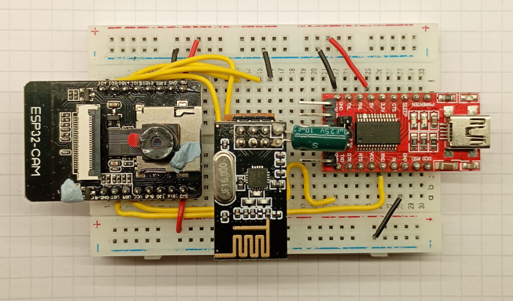
The transmitter consists of an AI-Thinker ESP32-CAM, an nRF24L01 transceiver, and an FTDI USB adapter for programming.
Not pictured are the flying ground leads used to enter boot mode and reset.
The connections for the ESP32-CAM are as follows:
- ESP32-CAM 5V -> FTDI 5V
- ESP32-CAM GND -> FTDI GND
- ESP32-CAM UOT -> FTDI RX
- ESP32-CAM UOR -> FTDI TX
- ESP32-CAM IO13 -> nRF24 MOSI
- ESP32-CAM IO12 -> nRF24 MISO
- ESP32-CAM IO14 -> nRF24 SCK
- ESP32-CAM IO15 -> nRF24 CSN
- ESP32-CAM IO02 -> nRF24 CE
The pin markings on your modules might vary slightly depending on the supplier.
Receiver & Display
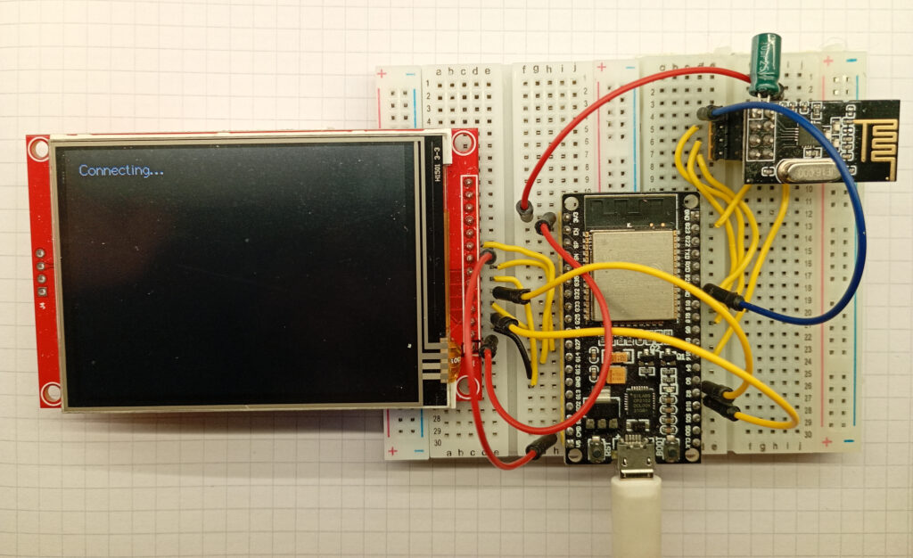
The receiver uses an ESP-WROOM-32, connected to an nRF24L01 transceiver module and a 320×240 pixel TFT display with the ILI9341 driver chip.
The display comes with a resistive touch screen, but these pins have not been used.
The connections for the ESP-WROOM-32 are as follows:
- ESP32 3V3 -> nRF24 Vcc
- ESP32 GND -> nRF24 GND
- ESP32 IO23 -> nRF24 MOSI
- ESP32 IO19 -> nRF24 MISO
- ESP32 IO18 -> nRF24 SCK
- ESP32 IO4 -> nRF24 CSN
- ESP32 IO5 -> nRF24 CE
- ESP32 3V3-> ILI9341 Vcc
- ESP32 GND-> ILI9341 GND
- ESP32 IO15 -> ILI9341 CS
- ESP32 IO27 -> ILI9341 RST
- ESP32 IO2 -> ILI9341 D/C
- ESP32 IO13 -> ILI9341 SDI/MOSI
- ESP32 IO14 -> ILI9341 SCK
- ESP32 3V3 or 5V* -> ILI9341 LED
- ESP32 IO12 -> ILI9341 SDO/MOSI
The pinout for the nRF24L01 module can be found here, along with some test code for the radio modules. The modules I’m using in this test have been fitted with a 10uF capacitor directly soldered to the VCC and GND pins of the module. I strongly recommend starting with a radio connection and building the project from there.
Similarly, *here is a page which shows the difference in screen brightness between using 3.3V and 5V voltage on the ILI9341 LED pin.
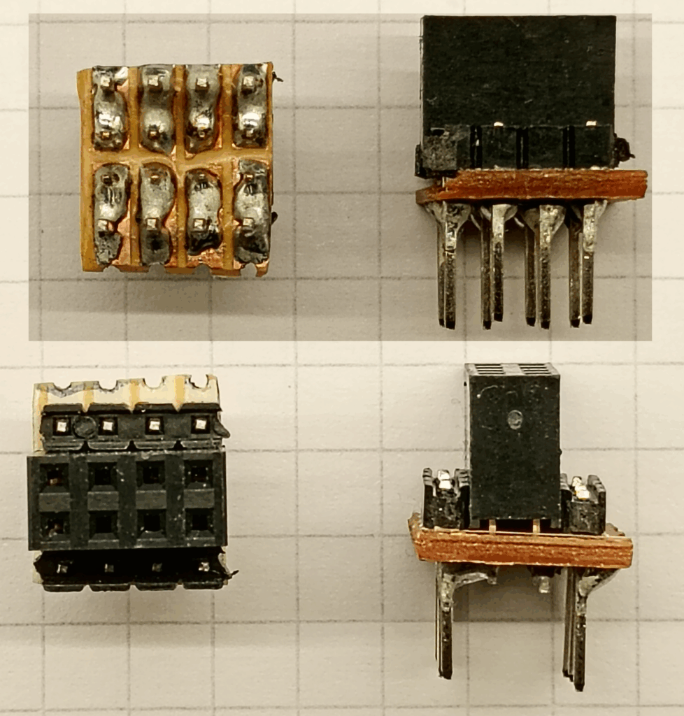
As the standard 2×4 pin arrangement of the nRF24 module is not compatible with a typical breadboard, I have fabricated a pair of custom adapters.
These are made from a simple 4×4 grid of prototyping board bisected perpendicularly, and fitted with a female 4×2 female pin socket, and two rows of modified male pins.
The male pins were standard pin headers, but the plastic spacers had pushed to the far end of the pin.
Software
Preface – Theory of Operation
The maximum payload of the nRF24 module is 32 bytes, and a full frame image at QVGA resolution is 153,600 bytes, so the image needs to be deconstructed before transmission, and reassembled upon receipt at the other end before being displayed on the screen.
To achieve this, the 76,800 pixels are subdivided in to 5,120 “chunks” of 15 pixels, with each chunk having a unique identifier. At the other end, the chunk identifier is used to locate the pixels X & Y co-ordinates. I’ve attempted to convey this pictorially via the medium of excel.
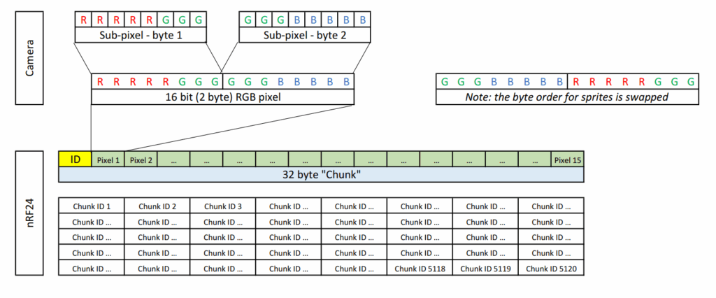
The benefit of this system is that it is robust against lost data packets – the image will simply load what is received – nothing more, nothing less. This is also a simple system that has no error correction as that’s catered for by the “enhanced shockburst protocol” by Nordic Semiconductors used on the nRF24 modules.
Code – UserSetup.h
As the display uses the TFT_eSPI library, the UserSetup.h file needs to be correctly configured. The code below gives the correct pinouts allowing the display to work. Please note that this only includes font number 2 – uncomment the relevant line to unlock more.
#define USER_SETUP_INFO "User_Setup"
#define ILI9341_DRIVER       // Generic driver for common displays
#define TFT_SDA_READ      // This option is for ESP32 ONLY, tested with ST7789 and GC9A01 display only

//  #define TFT_RGB_ORDER TFT_RGB  // Colour order Red-Green-Blue
#define TFT_RGB_ORDER TFT_BGR  // Colour order Blue-Green-Red

#define TFT_MISO 12
#define TFT_MOSI 13		//changed TO this pin on 2023 01 06
#define TFT_SCLK 14		//changed TO this pin on 2023 01 06
#define TFT_CS   15  // Chip select control pin
#define TFT_DC    2  // Data Command control pin
#define TFT_RST   27  // Reset pin (could connect to RST pin)
//#define TFT_RST  -1  // Set TFT_RST to -1 if display RESET is connected to ESP32 board RST
//#define TOUCH_CS 21     // Chip select pin (T_CS) of touch screen

//#define LOAD_GLCD   // Font 1.
#define LOAD_FONT2  // Font 2.
//#define LOAD_FONT4  // Font 4.
//#define LOAD_FONT6  // Font 6. only characters 1234567890:-.apm
//#define LOAD_FONT7  // Font 7. only characters 1234567890:-.
//#define LOAD_FONT8  // Font 8. only characters 1234567890:-.
//#define LOAD_FONT8N // Font 8. Alternative to Font 8
//#define LOAD_GFXFF  // FreeFonts.
//#define SMOOTH_FONT

// #define SPI_FREQUENCY   1000000
// #define SPI_FREQUENCY   5000000
// #define SPI_FREQUENCY  10000000
// #define SPI_FREQUENCY  20000000
// #define SPI_FREQUENCY  27000000
#define SPI_FREQUENCY  40000000
// #define SPI_FREQUENCY  55000000 // STM32 SPI1 only (SPI2 maximum is 27MHz)
// #define SPI_FREQUENCY  80000000

// Optional reduced SPI frequency for reading TFT
#define SPI_READ_FREQUENCY  20000000

// The XPT2046 requires a lower SPI clock rate of 2.5MHz so we define that here:
#define SPI_TOUCH_FREQUENCY  2500000
#define SUPPORT_TRANSACTIONS
Code – Camera & Transmitter
#include <SPI.h>
#include <nRF24L01.h>
#include <RF24.h>
#include <printf.h>

#include "esp_camera.h"

#define CAMERA_MODEL_AI_THINKER
#define PWDN_GPIO_NUM     32
#define RESET_GPIO_NUM    -1
#define XCLK_GPIO_NUM      0
#define SIOD_GPIO_NUM     26
#define SIOC_GPIO_NUM     27
#define Y9_GPIO_NUM       35
#define Y8_GPIO_NUM       34
#define Y7_GPIO_NUM       39
#define Y6_GPIO_NUM       36
#define Y5_GPIO_NUM       21
#define Y4_GPIO_NUM       19
#define Y3_GPIO_NUM       18
#define Y2_GPIO_NUM        5
#define VSYNC_GPIO_NUM    25
#define HREF_GPIO_NUM     23
#define PCLK_GPIO_NUM     22

//radio setup
const int CEpin = 2;
const int CSNpin = 15;
RF24 radio(CEpin, CSNpin); // CE, CSN
const byte address[] = "00001";

//camera setup
camera_config_t config;
uint16_t *scr;

void setup() {

  Serial.begin(115200);
  printf_begin();
  psramInit();

  //radio start
  SPI.begin(14, 12, 13, 15);
  if (!radio.begin()) {
    Serial.println(F("radio hardware not responding!"));
    while (1) {}
  }

  radio.setAutoAck(false);
  radio.setChannel(115);
  radio.setPALevel(RF24_PA_LOW);
  radio.setDataRate(RF24_2MBPS);
  radio.openWritingPipe(address);
  radio.stopListening();
  //radio.printPrettyDetails();

  //camera start
  config.ledc_channel = LEDC_CHANNEL_0;
  config.ledc_timer = LEDC_TIMER_0;
  config.pin_d0 = Y2_GPIO_NUM;
  config.pin_d1 = Y3_GPIO_NUM;
  config.pin_d2 = Y4_GPIO_NUM;
  config.pin_d3 = Y5_GPIO_NUM;
  config.pin_d4 = Y6_GPIO_NUM;
  config.pin_d5 = Y7_GPIO_NUM;
  config.pin_d6 = Y8_GPIO_NUM;
  config.pin_d7 = Y9_GPIO_NUM;
  config.pin_xclk = XCLK_GPIO_NUM;
  config.pin_pclk = PCLK_GPIO_NUM;
  config.pin_vsync = VSYNC_GPIO_NUM;
  config.pin_href = HREF_GPIO_NUM;
  config.pin_sscb_sda = SIOD_GPIO_NUM;
  config.pin_sscb_scl = SIOC_GPIO_NUM;
  config.pin_pwdn = PWDN_GPIO_NUM;
  config.pin_reset = RESET_GPIO_NUM;
  config.xclk_freq_hz = 20000000;
  config.frame_size = FRAMESIZE_QVGA;
  config.pixel_format = PIXFORMAT_RGB565;
  config.grab_mode = CAMERA_GRAB_LATEST;
  config.fb_location = CAMERA_FB_IN_PSRAM;
  config.jpeg_quality = 12;
  config.fb_count = 2;

  esp_err_t err = esp_camera_init(&config);
  sensor_t * s = esp_camera_sensor_get();
  s->set_brightness(s, 0);     // -2 to 2
  s->set_contrast(s, 0);       // -2 to 2
  s->set_saturation(s, 0);     // -2 to 2
  s->set_special_effect(s, 0); // 0 to 6
  s->set_whitebal(s, 1);
  s->set_awb_gain(s, 1);
  s->set_wb_mode(s, 0);        // 0 to 4
  s->set_exposure_ctrl(s, 1);
  s->set_aec2(s, 0);
  s->set_ae_level(s, 0);       // -2 to 2
  s->set_aec_value(s, 300);    // 0 to 1200
  s->set_gain_ctrl(s, 1);
  s->set_agc_gain(s, 0);       // 0 to 30
  s->set_gainceiling(s, (gainceiling_t)0);  // 0 to 6
  s->set_bpc(s, 0);
  s->set_wpc(s, 1);
  s->set_raw_gma(s, 1);
  s->set_lenc(s, 1);
  s->set_hmirror(s, 0);
  s->set_vflip(s, 0);
  s->set_dcw(s, 1);
  s->set_colorbar(s, 0);

  Serial.println("end of setup");
  delay(100);

}

void loop() {

  uint16_t *frame_buffer = (uint16_t *) ps_malloc(76800 * sizeof(uint16_t));

  //take picture
  camera_fb_t * fb = NULL;
  fb = esp_camera_fb_get();
  //transfer camera frame to buffer
  for (int i = 0; i < 76800; i++) {
    byte first_byte = fb->buf[i * 2];
    byte second_byte = fb->buf[i * 2 + 1];
    //frame_buffer[i] = (second_byte << 8) + first_byte;
    frame_buffer[i] = (first_byte << 8) + second_byte;
  }

  //send image in 32byte chunks
  //1 chunk = 2byte preamble ID + 30bytes of data (15pixels)
  //1 frame = 320x240 pixels = 76800pixels
  //76800 x 2byte (16bit RGB) = 153600 bytes total
  //153600 / 30byte chunk = 5120 chunks

  struct Chunk {
    uint16_t chunk_id;
    uint16_t pixel_data[15];
  };

  Chunk data;

  for (int i = 0; i < 5120; i++) {
    data.chunk_id = i;

    for (int j = 0; j < 15; j++) {
      data.pixel_data[j] = frame_buffer[((15 * i) + j)];
    }
    radio.write(&data, sizeof(Chunk));
  }

  //free up memory and report to serial
  esp_camera_fb_return(fb);
  free(frame_buffer);

}
Libraries, Definitions, Globals & Constructors
The pin definitions are based on the AI-thinker version of the ESP32-CAM.
Setup ( )
In order to remap the pins for the nRF24 module, it is imperative that the SPI.begin( ) function is BEFORE the radio.begin( ) function. Failure to do so will yield a “hardware not responding” error on the serial monitor.
Loop ( )
Simple!
Step 1: take a photo, load the sub-pixel data into a 16bit buffer on the PSRAM.
Step 2: Run a for( ) loop for 5120 iterations, with each iteration containing an ID and 15 pixels of the image from PSRAM
Step 3: Return the memory from whence it came, and repeat ad infinitum.
Code – Receiver & Display
#include <SPI.h>
#include <nRF24L01.h>
#include <RF24.h>
#include <printf.h>
#include <TFT_eSPI.h>

TFT_eSPI tft = TFT_eSPI();
//TFT_eSprite spr = TFT_eSprite(&tft);

//uint16_t *scr;

const int CEpin = 5;
const int CSNpin = 4;
const byte address[] = "00001";

RF24 radio(CEpin, CSNpin); // CE, CSN

struct Chunk {
  uint16_t chunk_id;
  uint16_t pixel_data[15];
};

Chunk data;

long chunkCount = 0;
long previousChunkLocation = -1;
long frameTime = 0;
long previousFrameTime = 0;

void setup() {
  Serial.begin(115200);
  printf_begin();

  tft.init();
  tft.setRotation(1);
  tft.fillScreen(TFT_BLACK);
  tft.setTextColor(TFT_WHITE);
  //scr = (uint16_t*)spr.createSprite(320, 240);
  tft.drawString(String("Connecting..."), 10, 10, 2 );

  delay(1000);

  if (!radio.begin()) {
    Serial.println(F("radio hardware not responding!"));
    while (1) {}
  }

  radio.setAutoAck(false);
  radio.setChannel(115);
  radio.setPALevel(RF24_PA_LOW);
  radio.setDataRate(RF24_2MBPS);
  radio.openReadingPipe(1, address);
  radio.startListening();
  radio.printPrettyDetails();
  bool result = radio.isChipConnected();
  Serial.println(result);

}

void loop() {
    if (radio.available()) {
    radio.read(&data, sizeof(Chunk));
    chunkCount++;

    long chunk_location = data.chunk_id * 15;
    long pixel_no;
    //Serial.println(chunk_location);

    for (int i = 0; i < 15; i++) {
      //scr[chunk_location + i] = data.pixel_data[i];
      pixel_no = chunk_location + i;
      int pixel_x = pixel_no % 320;
      int pixel_y = pixel_no / 320;
      tft.drawPixel(pixel_x, pixel_y, data.pixel_data[i]);
    }

    //Serial.print(chunk_location);   Serial.print(",");    Serial.println(millis());

    if (chunk_location < previousChunkLocation) {
      frameTime = millis() - previousFrameTime;
      Serial.print(chunkCount);   Serial.print(" pixel per ");  Serial.print(frameTime);    Serial.println(" ms");
      chunkCount = 0;
      previousFrameTime = millis();
    }

    previousChunkLocation = chunk_location;

    /*    if (chunk_location < previousChunkLocation) {
          spr.pushSprite(0, 0);
          frameTime = millis()-previousFrameTime;
          Serial.print(chunkCount);   Serial.print("in ");  Serial.println(frameTime);
          chunkCount = 0;
          previousFrameTime = millis();
        }
        previousChunkLocation = chunk_location;
    */
  }
}
Libraries, Definitions, Globals & Constructors
Much the same as previous, but the camera is swapped for a TFT display, and the nRF24 pins are different. So I guess, it’s nothing like the previous.
Setup( )
This code has the ghosts of the previous experiments using sprites – these have been commented out. Uncomment at your own peril.
TFT.setRotation( ) should either be 1 or 3 for a landscape image. 5 and 7 might also work, but I dunno.
Loop( )
Simple, again!
Step 1: Check if the nRF24 module has received anything. If not then check again.
Step 2: If the radio has received a chunk, then calculate it’s location and commit the pixel data from the chunk to the next 15 pixels on the display.
Step 3: If the chunk ID is lower than the previous chunk then that would signify a new frame; thus report the analytics data to the serial monitor and continue as normal.
Conclusion & Future Plans
If you’ve been following this far then hopefully you should have something that performs similarly to the video below, sans the random bespectacled chap.
There is no getting away from the fact that the frame rate is slow as balls. While drawing the image as a constant tft.drawPixel( ) isn’t efficient, the bottleneck is with the radio communications.
My understanding of the ESB protocol is that there are an additional 27 bytes of overheads per 32 byte “chunk”, adding an extra 138,240 bytes to the transmission of a single frame, giving a total of 302,080 bytes. This is achieved in 2,225 milliseconds, therefore giving a transmission rate of 1.08 Mbps – nearly half of the 2Mbps claimed!!
As with most things I do, there is often an ulterior motive; and this is no exception. Since February 2024, I’ve been wanting to do some tests with various nRF24 modules, and this “coincidentally” provides the perfect test rig.
Page created: 21/11/2025
Last updated: 22/11/2025