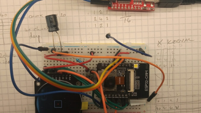
After finding myself with a little extra time over the festive period, I decided to go back over the ESP32-CAM homebrew computer vision project after a few months hiatus.
Thankfully, the resource page for getting the ESP32-CAM and the GC9A01 display working was a real helping hand, as was the previous blog post about shifting the camera duty to one dedicated CPU core. The other blog post about exporting pixel data to excel was very handy for debugging.
The Plan:
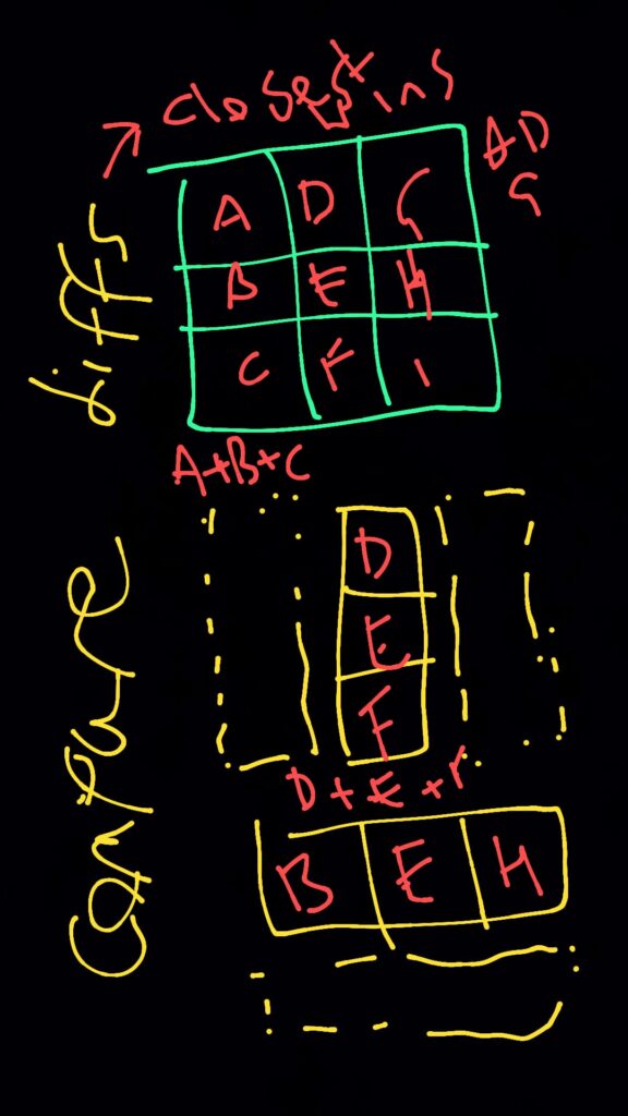
At 10:26pm on Monday 9th September, while in bed, the idea came to me and I scribbled the following bollocks on to a black photo on WhatsApp and sent it to myself.
The theory is to use a pair of single dimensional kernels using data from the new image frame and convolute them perpendicularly over the previous image frame, calculating the sum of the differences between the two frames.
Which ever column and row had the lowest total difference would be the closest match and thus indicate the deviation along the X & Y axis between the two frames.
If there was no difference between the two images then the central most column and row would match the new frame data and thus ΔX & ΔY would be zero.
How hard could it be?…
The Execution
Being painfully aware of the humble processing power of an ESP32-S, there was a great deal of consideration given to speed over accuracy. Ultimately, the camera and display was averaging a 80ms refresh rate (12.5FPS), so there is no use if the algorithm takes >100ms to process a frame.
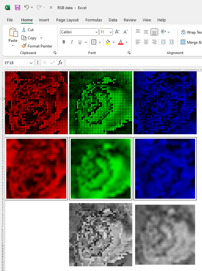
These cuts include (but are not limited to) reducing the field of view to 40×40 pixels and operating using the separate RBG channels, rather than calculating a single greyscale (However, I might revise that*).
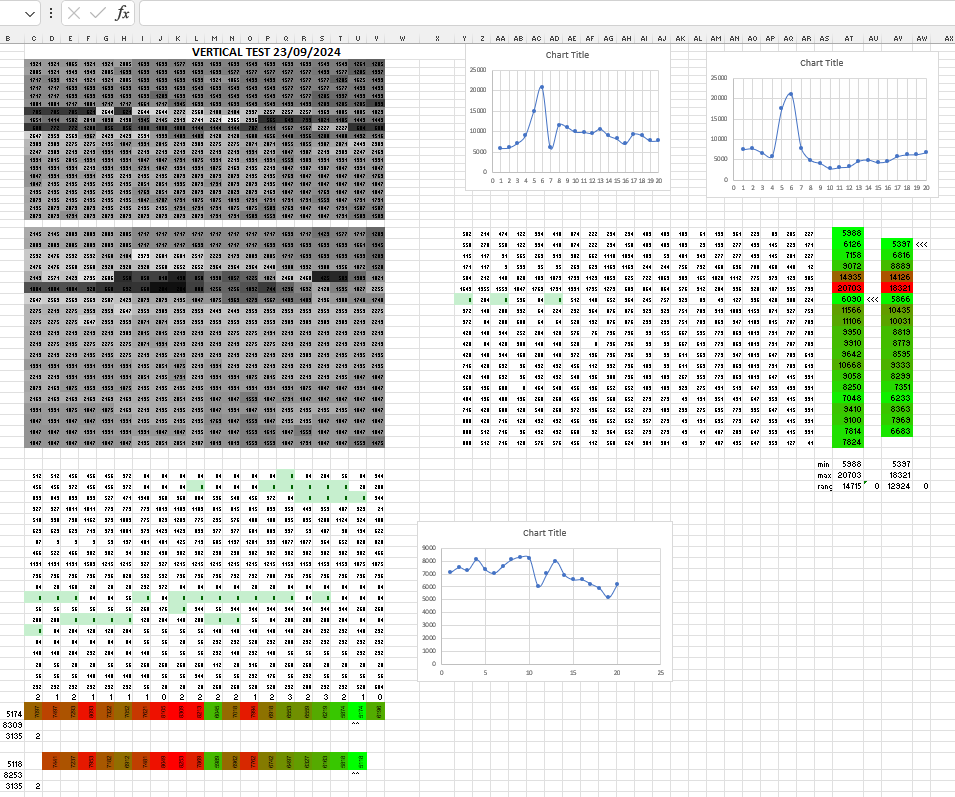
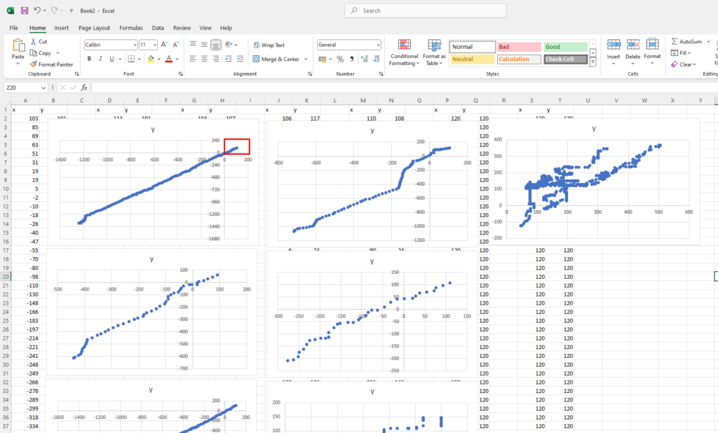
To be honest, the true tedium of the task can be summed up in the images below; which are just screenshots of tests done in Excel.
The Results
Prepare to be underwhelmed. The below video is the real-time output showing the best results the algorithm could achieve. Multiple takes were done and yes, this was the best 19 seconds out of nearly 2 minutes of footage.
As with every foray into a new specialism; failure is inevitable and it’s important to look for the good bits amongst the mountains of shit.
The second video is slowed to 30% speed and cut to show just the “good bits”.
You can see that there are a couple of frames where the red dot moves in time with the background: IT IS TRACKING MOVEMENT!
To me this is a win for homebrew computer vision.
Update: 07/01/2024
So after writing this post; I decided to polish this turd a bit; firstly by adding a timer on core_0 to measure the refresh rate: as mentioned earlier, no point trying if the the data cannot be processed in time.
The original RGB code was taking about 9ms to process, and a further 71ms waiting for the camera to capture a new frame, giving a duty of about 11%.
*Changing the code to greyscale reduced the processing time further to a mere 4ms (5%) while also helping with accuracy.
Convoluting a 3×3 box blur kernel over the frames also smoothed some noise, while still keeping the duty of the CPU core at about 10%.
For some reason; out of all of the “objects” that were tested, the most successfully tests were carried out using my forehead as a target: ominous.
The Future
After reviewing the footage; it’s easy to see that the motion is only tracked when there is perpendicular motion. This is a major downfall to the algorithm as the single dimension kernels go out of phase if there is any parallel offset (let alone any rotational movement!).
I have plans to experiment with other blurring kernels to try and mitigate the parallel phase offset. In addition to this, I would also like to experiment with larger/multiple scan areas, or just fucking-off this flawed algorithm and starting again with a completely different method.
I’m not openly sharing the code (out of embarrassment) as there is enough trash on the internet without me adding to it; but if you’re interested then drop me a message on the contact page and I’ll send it to you.