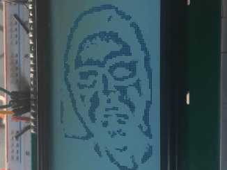
An Exercise in Futility: Edge detection on a ST7920 128×64 LCD display
Ever since doing the successful real-time edge detection experiment using the GC9A01 display, I couldn’t help but wonder what it would be like on the […]
Ever since doing the successful real-time edge detection experiment using the GC9A01 display, I couldn’t help but wonder what it would be like on the […]

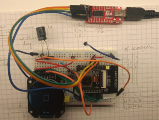
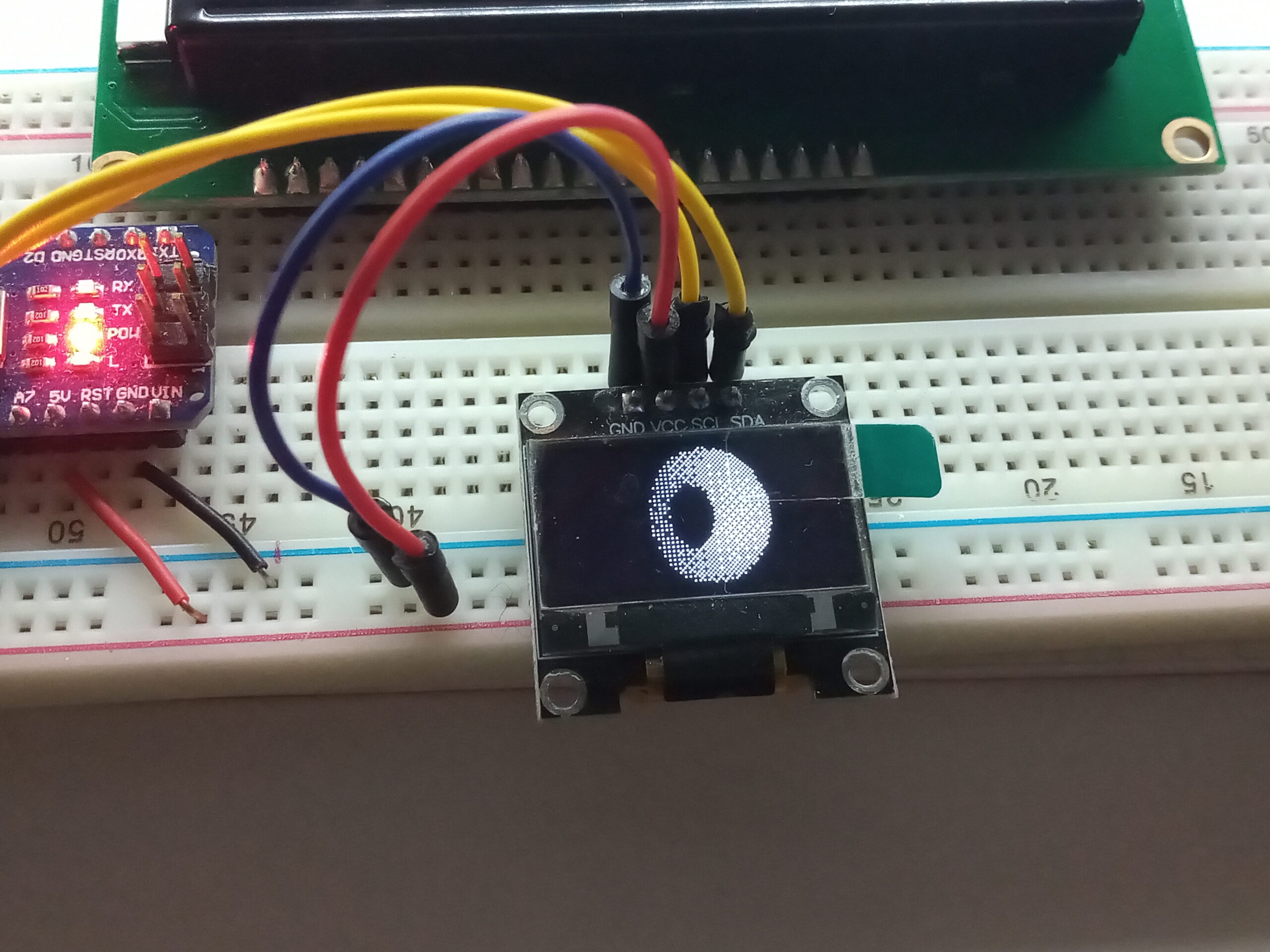
This project builds on the experience gained during the previous motion tracking ESP32-CAM project, and is simply just a proof-of-concept to see if the ESP32 […]
After finding myself with a little extra time over the festive period, I decided to go back over the ESP32-CAM homebrew computer vision project after […]
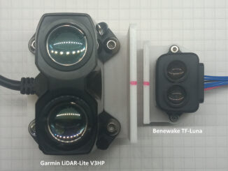
I’ve previously tested beam divergence of the Benewake TF-Luna as part of the VL6180X distance sensor write-up, which also includes results from the Sharp IR […]
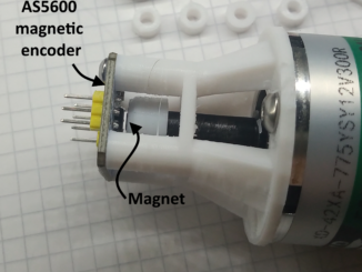
Curiosity is a strong driving force; especially, when there is a note on the datasheet regarding braking and PWM control. You can see the note […]
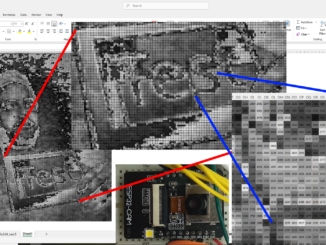
This is a post about how to export image data from an ESP32-CAM via serial, and how to them import it in to Microsoft Excel
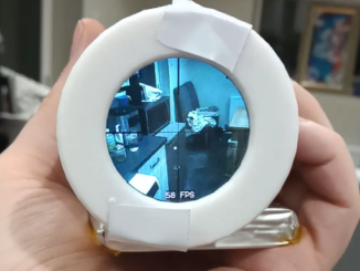
This uses the same setup as the original experiment which achieved 32FPS by splitting the duty across the two CPU cores. However, as this only […]
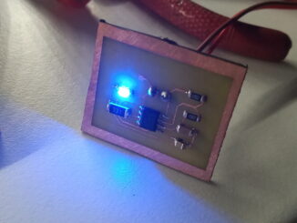
Currently, all of the electronics in my projects are made using copper strip board (vero board). This is great for through-hole components, and larger SMD […]
This started as the result of misreading the title of a Reddit post by u/Trotztd and lead to rendering 3D graphics on an Arduino. The […]
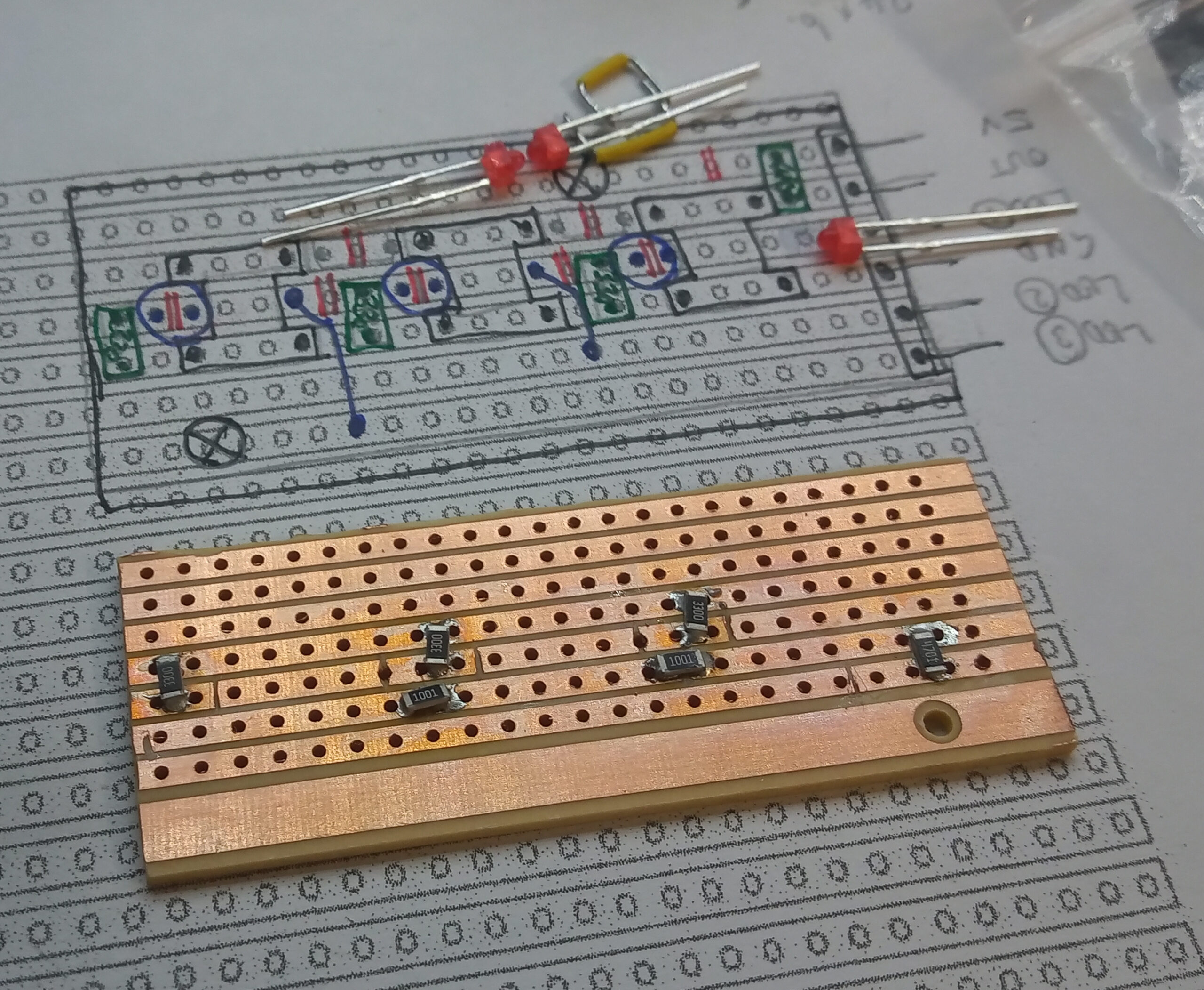
When prototyping, my preferred protoboard is Verobaord/Stripboard as it has handy 2mm wide copper busses set at a 2.54mm (0.1inch) pitch. As a result, there […]
Copyright © 2025 | WordPress Theme by MH Themes