This project builds on the experience gained during the previous motion tracking ESP32-CAM project, and is simply just a proof-of-concept to see if the ESP32 is fast enough to do kernel convolutions in real time.
Hardware
As with the previous project, this project uses the AI-Thinker ESP32-CAM with the OV2640 camera module with the GC9A01 circular 240×240 pixel display. An FDTI adapter is used for programming the ESP32-CAM.
The below image shows the wiring – please ignore the pushbutton in this setup. More pinout information can be found on the specific resource page.
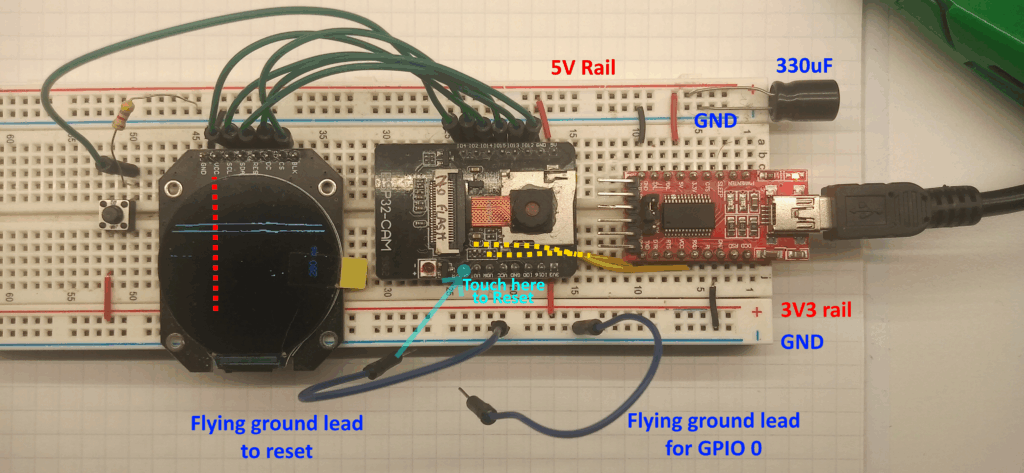
I’ve found that loose wires between the FTDI adapter and ESP32-CAM can cause a flickering screen and unintentional restarts, therefore I’ve soldered pin headers to the FTDI for a more solid mounting in a breadboard.
You can restart the ESP32-CAM by grounding the GPIO pin closest to the flash. Some solder masks note this as “GND/R”. An extra flying led is useful for tying GPIO 0 to ground to enter download mode.
Oh yeah, this uses the PSRAM, so GPIO16 is off limits.
Software.
The basic principal of operation is:
- The camera grabs an 8-bit greyscale image.
- The ESP32 transfers this image to a buffer stored on the PSRAM
- A Gaussian blur kernel is convoluted over the image, with the output going to another buffer in the PSRAM.
- The blurred image is then passed over by a Laplacian edge detection kernel, again with the output going to a buffer stored on the PSRAM.
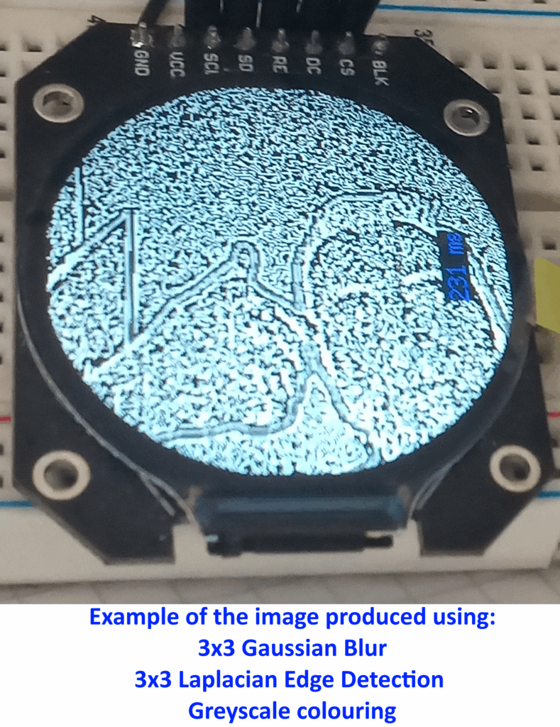
The code below includes variations for both the 3×3 and 5×5 Gaussian and Laplacian kernels. There is also an alternative colouring algorithm included which produces a greyscale image on the display.
Simply copying and pasting all of the code below will not work, you need to select which filters you want to apply and alter the code to suit.
#include "esp_camera.h"
#include <TFT_eSPI.h> // CHECK YOUR User_Setup.h File.
#include <SPI.h>

#define CAMERA_MODEL_AI_THINKER
#define PWDN_GPIO_NUM     32
#define RESET_GPIO_NUM    -1
#define XCLK_GPIO_NUM      0
#define SIOD_GPIO_NUM     26
#define SIOC_GPIO_NUM     27
#define Y9_GPIO_NUM       35
#define Y8_GPIO_NUM       34
#define Y7_GPIO_NUM       39
#define Y6_GPIO_NUM       36
#define Y5_GPIO_NUM       21
#define Y4_GPIO_NUM       19
#define Y3_GPIO_NUM       18
#define Y2_GPIO_NUM        5
#define VSYNC_GPIO_NUM    25
#define HREF_GPIO_NUM     23
#define PCLK_GPIO_NUM     22

TFT_eSPI tft = TFT_eSPI();
TFT_eSprite spr = TFT_eSprite(&tft);
uint16_t *scr;

camera_config_t config;
camera_fb_t  * fb;

long initalTime = 0;
long frameTime = 0;
Libraries, Definitions and Globals
This uses the TFT_eSPI library which requires a custom UserSetup.h file. This can be found on the resource page for the ESP32-CAM and GC9A01 display.
The pin definitions are standard to the AI Thinker board. If you’re using different hardware then these need changing.
The display object is created, along with a sprite called ‘spr’ which is where the final frame is stored before being displayed.
The camera is set up using the configuration detailed in the setup( ) function.
void setup() {
  psramInit();
  Serial.begin(115200);

  tft.init();
  tft.setRotation(3);
  tft.fillScreen(TFT_BLACK);
  tft.setTextColor(TFT_BLACK, TFT_WHITE);

  //scr = (uint16_t*)spr.createSprite(236, 236); //for 3x3
  scr = (uint16_t*)spr.createSprite(232, 232);  //for 5x5

  config.ledc_channel = LEDC_CHANNEL_0;
  config.ledc_timer = LEDC_TIMER_0;
  config.pin_d0 = Y2_GPIO_NUM;
  config.pin_d1 = Y3_GPIO_NUM;
  config.pin_d2 = Y4_GPIO_NUM;
  config.pin_d3 = Y5_GPIO_NUM;
  config.pin_d4 = Y6_GPIO_NUM;
  config.pin_d5 = Y7_GPIO_NUM;
  config.pin_d6 = Y8_GPIO_NUM;
  config.pin_d7 = Y9_GPIO_NUM;
  config.pin_xclk = XCLK_GPIO_NUM;
  config.pin_pclk = PCLK_GPIO_NUM;
  config.pin_vsync = VSYNC_GPIO_NUM;
  config.pin_href = HREF_GPIO_NUM;
  config.pin_sscb_sda = SIOD_GPIO_NUM;
  config.pin_sscb_scl = SIOC_GPIO_NUM;
  config.pin_pwdn = PWDN_GPIO_NUM;
  config.pin_reset = RESET_GPIO_NUM;
  config.xclk_freq_hz = 20000000;
  config.frame_size = FRAMESIZE_240X240;
  config.pixel_format = PIXFORMAT_GRAYSCALE;
  config.grab_mode = CAMERA_GRAB_LATEST;
  config.fb_location = CAMERA_FB_IN_PSRAM;
  config.jpeg_quality = 12;
  config.fb_count = 2;

  esp_err_t err = esp_camera_init(&config);

  sensor_t * s = esp_camera_sensor_get();
  s->set_brightness(s, 0);     // -2 to 2
  s->set_contrast(s, 0);       // -2 to 2
  s->set_saturation(s, 0);     // -2 to 2
  s->set_special_effect(s, 0); // 0 to 6 (0 - No Effect, 1 - Negative, 2 - Grayscale, 3 - Red Tint, 4 - Green Tint, 5 - Blue Tint, 6 - Sepia)
  s->set_whitebal(s, 1);       // 0 = disable , 1 = enable
  s->set_awb_gain(s, 1);       // 0 = disable , 1 = enable
  s->set_wb_mode(s, 0);        // 0 to 4 - if awb_gain enabled (0 - Auto, 1 - Sunny, 2 - Cloudy, 3 - Office, 4 - Home)
  s->set_exposure_ctrl(s, 1);  // 0 = disable , 1 = enable
  s->set_aec2(s, 0);           // 0 = disable , 1 = enable
  s->set_ae_level(s, 0);       // -2 to 2
  s->set_aec_value(s, 300);    // 0 to 1200
  s->set_gain_ctrl(s, 1);      // 0 = disable , 1 = enable
  s->set_agc_gain(s, 0);       // 0 to 30
  s->set_gainceiling(s, (gainceiling_t)0);  // 0 to 6
  s->set_bpc(s, 0);            // 0 = disable , 1 = enable
  s->set_wpc(s, 1);            // 0 = disable , 1 = enable
  s->set_raw_gma(s, 1);        // 0 = disable , 1 = enable
  s->set_lenc(s, 1);           // 0 = disable , 1 = enable
  s->set_hmirror(s, 0);        // 0 = disable , 1 = enable
  s->set_vflip(s, 0);          // 0 = disable , 1 = enable
  s->set_dcw(s, 1);            // 0 = disable , 1 = enable
  s->set_colorbar(s, 0);       // 0 = disable , 1 = enable

  spr.setTextColor(TFT_BLUE, TFT_BLACK);
  tft.setTextColor(TFT_WHITE, TFT_BLACK);
  tft.drawString("Loading...", 105, 105, 2);
  delay(1000);
Setup
The setup function initialises the PSRAM, starts the serial communication and initialises the display.
The sprite size depends on the final image size, which depends on the size of the kernels and the amount of padding.
The initial frame is set at 240×240 pixels, as no padding is used then a 3×3 kernel will loose the outer most pixels, so two passes will loose the outer 2 most pixels, so the sprite needs to be set to 236×236.
For two passes of a 5×5 kernel, the outer 4 most pixels will be lost, so the sprite needs to be 232×232.
Note that there are certain camera settings: the frame size has been changed to 240×240, the pixel format is grayscale (0-255), and will grab the latest frame and store it in the PSRAM.
I’ve not played with the sensor settings, so there could be improvements with noise settings.
Finally, the display shows a “Loading…” sign for a second as a simple POST. If you don’t see the loading page then your problems are further up the pipe.
void loop() {

  initalTime = millis();

  //PS ram allocaions
  int *frame_buffer = (int *) ps_malloc(57600 * sizeof(int));
  //int *gaus_buffer = (int *) ps_malloc(56644 * sizeof(int));    //for 3x3 kernel
  //int *laplace_buffer = (int *) ps_malloc(55696 * sizeof(int)); //for 3x3 kernel
  int *gaus_buffer = (int *) ps_malloc(55696 * sizeof(int));      //for 5x5 kernel
  int *laplace_buffer = (int *) ps_malloc(53824 * sizeof(int));   //for 5x5 kernel

  //take photo
  fb = esp_camera_fb_get();

  //transfer camera frame to buffer
  for (int i = 0; i < 57600; i++) {
    frame_buffer[i] = fb->buf[i];
  }
Start of The Loop
This first part of the loop starts the frame timer and allocates the relevant sizes of PSRAM to the relevant buffers.
Note that there are different buffer sizes depending on the size of the kernels:
- 3×3 Gaussian = 56644 pixels
- 5×5 Gaussian = 55696 pixels
- 3×3 Laplacian = 55696 pixels
- 5×5 Laplacian = 53824 pixels
    //3x3 gausian filter, no padding, 1 step
    // 1 2 1
    // 2 4 2  * 1/16
    // 1 2 1
    for (int g = 0; g < 56644; g++) {

      int gx = (g % 238) + 1;
      int gy = (floor(g / 238)) + 1;
      int gf = (gy * 240) + gx;

      int gausSubTotal = 0;

      gausSubTotal += frame_buffer[gf - 241]; // * 1
      gausSubTotal += frame_buffer[gf - 240] * 2;
      gausSubTotal += frame_buffer[gf - 239]; // * 1

      gausSubTotal += frame_buffer[gf - 1] * 2;
      gausSubTotal += frame_buffer[gf] * 4;
      gausSubTotal += frame_buffer[gf + 1] * 2;

      gausSubTotal += frame_buffer[gf + 239]; // * 1
      gausSubTotal += frame_buffer[gf + 240] * 2;
      gausSubTotal += frame_buffer[gf + 241]; // * 1

      gaus_buffer[g] = gausSubTotal / 16;
    }
3×3 Gaussian Filter
This is the 3×3 Gaussian kernel with the weightings shown.
The relative x co-ordinate is worked out by using the modulo function, the relative y co-ordinate is calculated with the floor( ) function.
From this, the x & y co ordinates are mapped to the relevant pixel of the frame buffer.
The matrix multiplication is done by addressing relevant array elements by applying an offset to the original pixel. (Because the frame buffer is 240 pixels wide, an off set of +/- 240 would lead it to the pixel directly below or above).
  //5x5 gausian filter, no padding, 1 step
  //  1  4  6  4  1
  //  4 16 24 16  4
  //  6 24 36 24  6  * 1/256
  //  4 16 24 16  4
  //  1  4  6  4  1
  for (int g = 0; g < 55696; g++) {
    int gx = (g % 236) + 2;
    int gy = (floor(g / 236)) + 2;
    int gf = (gy * 240) + gx;
    int gausSubTotal = 0;

    gausSubTotal += frame_buffer[gf - 482]; // * 1
    gausSubTotal += frame_buffer[gf - 481] * 4;
    gausSubTotal += frame_buffer[gf - 480] * 6;
    gausSubTotal += frame_buffer[gf - 479] * 4;
    gausSubTotal += frame_buffer[gf - 478]; // * 1

    gausSubTotal += frame_buffer[gf - 242] * 4;
    gausSubTotal += frame_buffer[gf - 241] * 16;
    gausSubTotal += frame_buffer[gf - 240] * 24;
    gausSubTotal += frame_buffer[gf - 239] * 16;
    gausSubTotal += frame_buffer[gf - 238] * 4;

    gausSubTotal += frame_buffer[gf - 2] * 6;
    gausSubTotal += frame_buffer[gf - 1] * 24;
    gausSubTotal += frame_buffer[gf] * 36;
    gausSubTotal += frame_buffer[gf + 1] * 24;
    gausSubTotal += frame_buffer[gf + 2] * 6;

    gausSubTotal += frame_buffer[gf + 242] * 4;
    gausSubTotal += frame_buffer[gf + 241] * 16;
    gausSubTotal += frame_buffer[gf + 240] * 24;
    gausSubTotal += frame_buffer[gf + 239] * 16;
    gausSubTotal += frame_buffer[gf + 238] * 4;

    gausSubTotal += frame_buffer[gf + 482]; // * 1
    gausSubTotal += frame_buffer[gf + 481] * 4;
    gausSubTotal += frame_buffer[gf + 480] * 6;
    gausSubTotal += frame_buffer[gf + 479] * 4;
    gausSubTotal += frame_buffer[gf + 478]; // * 1

    gaus_buffer[g] = gausSubTotal / 256;
  }
5×5 Gaussian Filter
This uses the same principal as the above 3×3 filter, just with a larger kernel.
    //3x3 laplace filter, no padding, 1 step
    // -1 -1 -1
    // -1 +8 -1
    // -1 -1 -1
    for (int l = 0; l < 55696; l++) {
      int lapSubTotal = 0;

      int lx = (l % 236) + 1;
      int ly = (floor(l / 236)) + 1;

      int lf = (ly * 238) + lx;

      lapSubTotal += -gaus_buffer[lf - 239]; //  * -1
      lapSubTotal += -gaus_buffer[lf - 238]; //  * -1
      lapSubTotal += -gaus_buffer[lf - 237]; //  * -1
      lapSubTotal += -gaus_buffer[lf - 1]; //  * -1
      lapSubTotal += gaus_buffer[lf] * 8;
      lapSubTotal += -gaus_buffer[lf + 1]; //  * -1
      lapSubTotal += -gaus_buffer[lf + 237]; //  * -1
      lapSubTotal += -gaus_buffer[lf + 238]; //  * -1
      lapSubTotal += -gaus_buffer[lf + 239]; //  * -1

      laplace_buffer[l] = lapSubTotal;
    }
3×3 Laplacian Filter
This is designed to work on the 3×3 Gaussian filter and will likely throw an error if you try the 5×5 kernel.
  //5x5 laplace filter, no padding, 1 step
  // -1 -1 -1 -1 -1
  // -1 -1 -1 -1 -1
  // -1 -1 24 -1 -1
  // -1 -1 -1 -1 -1
  // -1 -1 -1 -1 -1
  for (int l = 0; l < 53824; l++) {
    int lapSubTotal = 0;
    int lx = (l % 232) + 2;
    int ly = (floor(l / 232)) + 2;
    int lf = (ly * 236) + lx;

    lapSubTotal += -gaus_buffer[lf - 474];
    lapSubTotal += -gaus_buffer[lf - 473];
    lapSubTotal += -gaus_buffer[lf - 472];
    lapSubTotal += -gaus_buffer[lf - 471];
    lapSubTotal += -gaus_buffer[lf - 470];

    lapSubTotal += -gaus_buffer[lf - 238];
    lapSubTotal += -gaus_buffer[lf - 237];
    lapSubTotal += -gaus_buffer[lf - 236];
    lapSubTotal += -gaus_buffer[lf - 235];
    lapSubTotal += -gaus_buffer[lf - 234];

    lapSubTotal += -gaus_buffer[lf - 2];
    lapSubTotal += -gaus_buffer[lf - 1];
    lapSubTotal += gaus_buffer[lf] * 24;
    lapSubTotal += -gaus_buffer[lf + 1];
    lapSubTotal += -gaus_buffer[lf + 2];

    lapSubTotal += -gaus_buffer[lf + 238];
    lapSubTotal += -gaus_buffer[lf + 237];
    lapSubTotal += -gaus_buffer[lf + 236];
    lapSubTotal += -gaus_buffer[lf + 235];
    lapSubTotal += -gaus_buffer[lf + 234];

    lapSubTotal += -gaus_buffer[lf + 474];
    lapSubTotal += -gaus_buffer[lf + 473];
    lapSubTotal += -gaus_buffer[lf + 472];
    lapSubTotal += -gaus_buffer[lf + 471];
    lapSubTotal += -gaus_buffer[lf + 470];

    laplace_buffer[l] = lapSubTotal;
  }
5×5 Laplacian Filter
Again, this is designed to be used with the previous 5×5 Gaussian kernel.
  //convert byte to RGB565 for 236x236px
    for (int s = 0;  s < 55696; s++) {
      uint8_t R = (laplace_buffer[s] >> 3) & 0x1F;
      uint8_t G = (laplace_buffer[s] >> 2) & 0x3F;
      uint8_t B = (laplace_buffer[s] >> 3) & 0x1F;
      uint16_t pixel = ((R << 11) | (G << 5) | B);
      int sx = (s % 236);
      int sy = (floor(s / 236));
      spr.drawPixel(sx, sy, pixel);
    }
Greyscale Conversion
This takes the result from the Laplacian filter (0-255) and converts it to greyscale by scaling the number to 5-bit red and blue components and a 6-bit green component to give to the RGB565 display.
This only works for the 236×236 frame after two 3×3 kernel passes. If you do two 5×5 kernel passes then the following needs to be altered:
- Counter ‘s’ in the for loop should be changed to 53824
- Change the modulo divisor to 232
- Change the floor divisor to 232
  //convert byte to RGB565 single bit for 232x232px
  for (int s = 0; s < 53824; s++) {
    uint16_t pixel;

    //midpoint threshold
    if (laplace_buffer[s] < 127) {
      pixel = 0;
    } else {
      pixel = 0xFFFF;
    }

    int sx = (s % 232);
    int sy = (floor(s / 232));
    spr.drawPixel(sx, sy, pixel);
  }
Threshold Conversion
This runs a simple if statement over every pixel and either turns them to zero if the value is below 127 or turns them to white if above 127.
This set up only works for the 232×232 frame after two 5×5 kernel passes. For two 3×3 passes change the following:
- For loop counter to 55696
- Modulo divisor to 236
- Floor divisor to 236
  spr.setCursor(100, 200, 2);
  spr.print(frameTime); spr.println(" ms");
  //spr.pushSprite(2, 2);
  spr.pushSprite(4, 4);

  esp_camera_fb_return(fb);
  free(frame_buffer);
  free(gaus_buffer);
  free(laplace_buffer);
  frameTime = millis() - initalTime;

}
End of the Loop
This final bit calculates the frame time, writes it to the sprite and then pushes the sprite to the screen.
Note that for two 3×3 kernel passes, the sprite should start at co-ordinates 2, 2. For two 5×5 kernel passes, the sprite co-ordinates are 4, 4.
Finally, all of the allocated memory is unallocated before the process is all started again.
Future Plans
This was just meant to test the output of the algorithms and to see if the ESP32 could even do a whole 240×240 frame without shitting a brick. I have no doubt that the frame rate could be increased by sharing the load with the other CPU core, but I’m going to go down a different route.
I would also like to give a shout out to Dewald Esterhuizen on https://softwarebydefault.com/ who shows more information in a much more elegant manner – this is the specific page which I found most useful for this: Laplacian of Gaussian | Software by Default
Leave a Reply