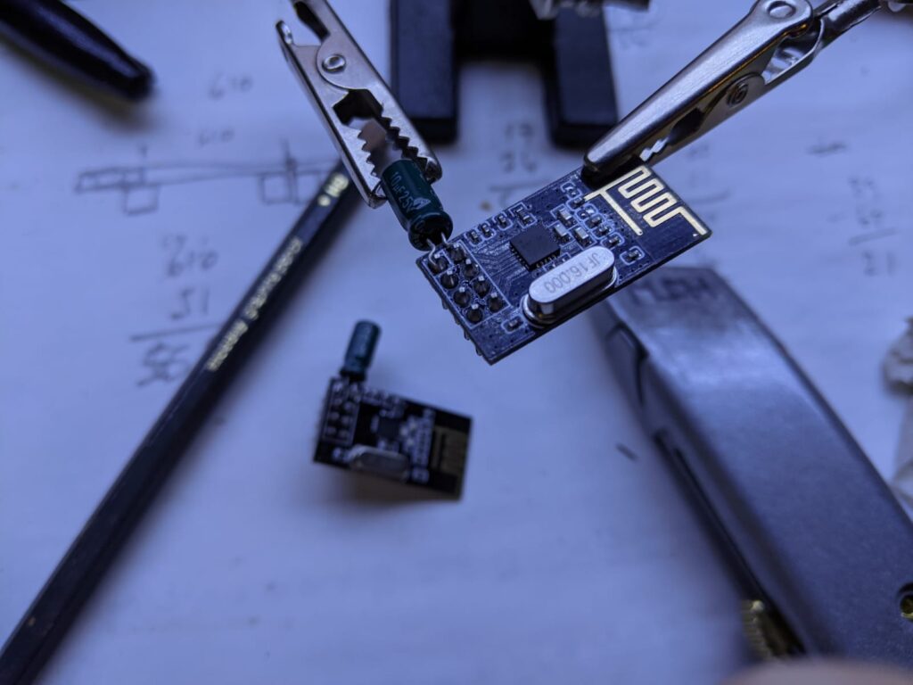
These are handy wireless modules featured in the weather station project and were used to transmit the sensor data. Theses transceivers were also used as the remote control for the robot project.
These modules are small, cheap and come with half-decent specifications. They’re capable of two-way communication, have a greater range than Bluetooth, are faster than 433Mhz and cheaper than LoRa.
That being said, these modules aren’t without their downsides. Troubleshooting and debugging often feels more like witchcraft than electronics. As such, any witchcraft that I’ve used will be in an italic font.
Hardware
The modules come in two main flavours; the first is smaller and has a PCB antenna, the second is larger and fitted with a physical antenna. Both types work interchangeably with each other, however you might have to tweak some settings*.
Both modules need to be attached to their own independent Arduinos. Consider how you’re going to power both Arduinos at the same time. For testing, I’ve done this by simply connecting two Arduinos to the laptop at the same time.
There are other types which have shielding. I’ve not tested these.
These modules are NOT COMPATIBLE WITH SD CARD READERS. I understand that this is due to the logic level converter on the MISO line on the SD module buggers the logic level for the nRF24L01 module. This problem is not present on data-logging shields for the Uno, despite the SD card reader.
Important Note: The module must be powered via the 3V3 rail from the Arduino. A logic level converter is not needed for the SPI pins.
Even more important note: these modules will not work properly without clean power*. I’ve not had much success with the small 5V compatible piggy-back modules that plug in to the rear of the module. When using the smaller modules; for any reliable transmission you’ll need to solder a 10uF capacitor across the GND & 3V3 pins.
One of the pitfalls with using witchcraft is the inevitable curses that come along with it. One of these curses seems to cause cats to be attracted to the modules (ask me how I know…). Make sure all wiring is secure and/or robust.
Pinout
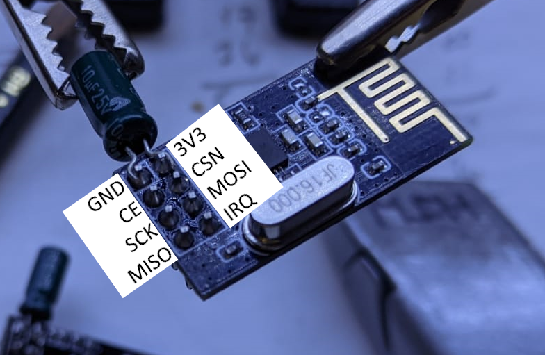
| GND | 3V3 |
| (D7 on Uno)(13 on ESP32) – CE | CSN – (D8 on Uno)(14 on ESP32) |
| (D13 on Uno)(18 on ESP32) – SCK | MOSI – (D11 on Uno)(23 on ESP32) |
| (D12 on Uno)(19 on ESP32) – MISO | (IRQ – not connected) |
Many other tutorials use pins 9 & 10 for the CE and CSN connections, however that blocks the standard chip select pin (D10) for other devices using the SPI bus.
Some modules have castellated solder joints on the one side of the board. If you’re looking for the pinout for those modules then you’ll need to look elsewhere.
Software – General Notes
Two sketches are need so there are twice the number of bugs. All credits kept in the original code.
*Lowering the PA_LEVEL to MIN can greatly increase the success rate of transmission, particularly for the larger modules without a capacitor soldered across the power pins. This setting will obviously reduce the range, but some range > no range. Disabling the AUTO_ACK reduce the number of headaches you develop.
Remember that any settings on the TX must be the same on the RX and vice-versa.
Test Code – One Way Transmission
This is the my most reliable code to test a pair of transceiver modules – connect each module as per the pinout above and plug both into your computer. Upload the code below to each microcontroller and open the COM port of the receiver to check for any transmissions.
Pro tip: put “TX” and “RX” stickers on the respective transceivers to help with any debugging.
Transmitter
/*
* Arduino Wireless Communication Tutorial
*     Example 1 - Transmitter Code
*
* by Dejan Nedelkovski, www.HowToMechatronics.com
*
* Library: TMRh20/RF24, https://github.com/tmrh20/RF24/
*/

#include <SPI.h>
#include <nRF24L01.h>
#include <RF24.h>
#include <printf.h>

RF24 radio(7, 8); // CE, CSN

const byte address[] = "00001";

void setup() {

  Serial.begin(9600);
  printf_begin();
  radio.begin();

if (!radio.begin()) {
  Serial.println(F("radio hardware not responding!"));
  while (1) {} // hold program in infinite loop to prevent subsequent errors
}


  radio.setAutoAck(false);
  radio.setChannel(115);
  radio.setPALevel(RF24_PA_LOW);

  radio.openWritingPipe(address);

  radio.stopListening();
  radio.printPrettyDetails();
}

void loop() {
  Serial.println("Entered TX loop");
  delay(150);
  const char text[] = "Hello World";
  radio.write(&text, sizeof(text));
  delay(1000);
}
Receiver
/*
* Arduino Wireless Communication Tutorial
*       Example 1 - Receiver Code
*
* by Dejan Nedelkovski, www.HowToMechatronics.com
*
* Library: TMRh20/RF24, https://github.com/tmrh20/RF24/
*/

#include <SPI.h>
#include <nRF24L01.h>
#include <RF24.h>
#include <printf.h>

RF24 radio(7, 8); // CE, CSN

const byte address[] = "00001";

void setup() {
  Serial.begin(9600);
  printf_begin();
  radio.begin();

if (!radio.begin()) {
  Serial.println(F("radio hardware not responding!"));
  while (1) {} // hold program in infinite loop to prevent subsequent errors
}


  radio.setAutoAck(false);
  radio.setChannel(115);
  radio.setPALevel(RF24_PA_LOW);

  radio.openReadingPipe(1, address);

  radio.startListening();
  radio.printPrettyDetails();
  bool result = radio.isChipConnected();
  Serial.println(result);

}

void loop() {
//Serial.println("in loop");
delay(1);
  if (radio.available()) {
    Serial.println("the radio is available");
    char value[32] = "";
    radio.read(&value, sizeof(value));
    Serial.println(value);
    delay(1);
    }
  }
If the above works first time then go out and buy a lottery ticket because you are the chosen one. For the rest of us mere mortals; I’ve discovered that checking the connections by pressing them with tear-coated fingers sometimes works.
One Way Transmission – Multiple Values
If you want to transmit multiple pieces of information then you can change the ‘value’ variable to an array.
The pinout for this test is a little more involved. In addition to connecting the nRF24 module, the transmitter also needs the wipers off two 10k pots connected to Uno pins A0 and A1.
Transmit – Multi
/*
* Arduino Wireless Communication Tutorial
*     Example 1 - Transmitter Code
*
* by Dejan Nedelkovski, www.HowToMechatronics.com
*
* Library: TMRh20/RF24, https://github.com/tmrh20/RF24/
*/

#include <SPI.h>
#include <nRF24L01.h>
#include <RF24.h>


RF24 radio(7, 8); // CE, CSN

const byte address[6] = "00001";
int value[] = {0,0};

//********************************

void setup() {

  Serial.begin(9600);

  pinMode(A0, INPUT);
  pinMode(A1, INPUT);

  radio.begin();


if (!radio.begin()) {
  while (1) {} // hold program in infinite loop to prevent subsequent errors
}


  radio.setChannel(115);
  radio.setPALevel(RF24_PA_MAX);

  radio.openWritingPipe(address);

  radio.stopListening();
  Serial.println("radio is ok TX");
}

//********************************

void loop() {


value[0] = analogRead(A0);
value[1] = analogRead(A1);

 radio.write(&value, sizeof(value));
 delay(20);


}
Receive – Multi
#include <SPI.h>
#include <nRF24L01.h>
#include <RF24.h>


RF24 radio(7, 8); // CE, CSN

const byte address[] = "00001";
int value[] = {0,0};

void setup() {
  Serial.begin(9600);

  radio.begin();

if (!radio.begin()) {
  Serial.println("radio hardware not responding!");
  while (1) {} // hold program in infinite loop to prevent subsequent errors
}


  radio.setChannel(115);
  radio.setPALevel(RF24_PA_MAX);

  radio.openReadingPipe(1, address);

  radio.startListening();

  bool result = radio.isChipConnected();


}

void loop() {


  if (radio.available()) {
        radio.read(&value, sizeof(value));
        Serial.print("x = ");
        Serial.print(value[0]);
        Serial.print(", y = ");
        Serial.println(value[1]);
        delay(1);
        }

}
I don’t know how the above code works. However, it has formed the backbone of any RC project used. The above code basically formed the foundation for the RC Robot project – allowing transmission of forward and reverse as well as side to side.
Future Plans
Using the above info, these modules will most likely be used for the future lawn mower project.
For that project, I would like to experiment with the shielded versions for improved reliability as well as setting up two-way communication for status monitoring.
First written: 08/10/2022
Last updated: 27/10/2023