
Ever since doing the successful real-time edge detection experiment using the GC9A01 display, I couldn’t help but wonder what it would be like on the larger* 128×64 pixel ST7920 LCD displays.
*larger in physical size, not in pixel count. In fact, the lower resolution comes as an advantage: the decreased pixel count decreases the amount of processing required per frame, so the frame rate on this is about 8.2-8.5 FPS.
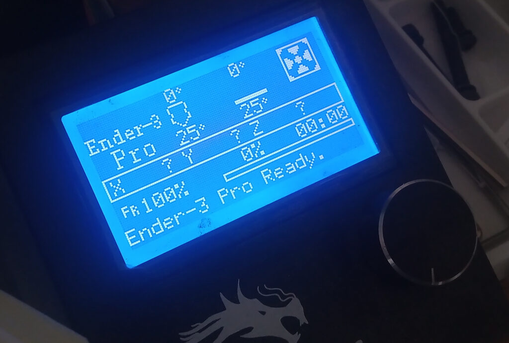
These are typically sold as 12864 graphical displays and are often used in budget 3D printers like my Ender 3-pro shown below.
Hardware
For full transparency: this is a 5V display. Originally, I connected it to the ESP32-CAM via a logic-level converter to take the values down to 3.3V, but the logic level converter was causing timing issues and did not work.
So trusting this guide by Floris Wouterlood, I connected the ESP32-CAM GPIO pins directly to the display and it seems to work! Thank you Floris!
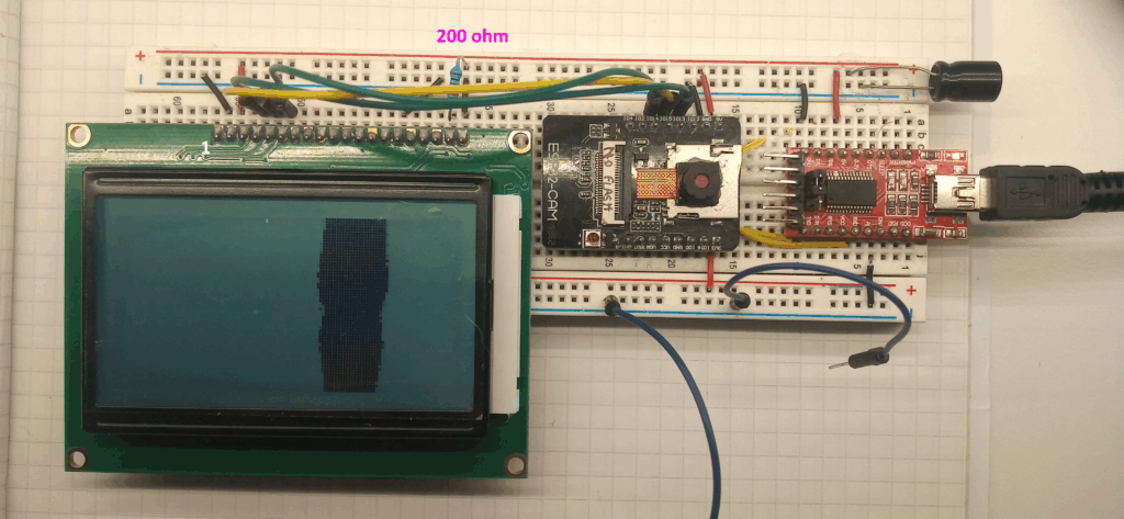
The display is used in 3-wire SPI mode, a full list of the connections can be found on the resource page. The capacitor value is 330uF – feel free experimenting with this, I don’t have a scope so can’t see how ‘noisy’ the powerline is.
Please note that because the PSRAM is in use, GPIO 16 is off limits. The display shares the same pins as the on-board SD card reader, so this cannot be used/will not work (or it might, I don’t know, I’ve not tried).
Software
This is a rehash of the 5×5 Laplacian of Gaussian kernel convolutional that was used in the previous edge detection project; the main difference is the display and camera resolutions.
The previous frame size was 240×240 pixels and the display was 240×240 pixels, so it just worked nicely. However, the new 128×64 pixel display would only cover a mere 14.2% of the camera frame if mapped 1:1 – this is what was done when previously using SH1106 display.
When doing kernel convolutions, you lose the information edge due to the size of the kernel. As such, the resolution was ‘back-ulated’ from the display resolution. Starting at 128×64 pixels, then adding the padding for the two 5×5 kernels gives a resolution of 136×72 pixels.
What is new is that this setup uses pixel subsampling, so it skips every other horizontal and vertical pixel. Applying this subsampling technique to the 136×72 pixels gives 272×144 effective frame size. This exceeds the previous 240×240 limit; therefore the camera resolution has been changed to QVGA (320×240 pixels), realising a coverage of 51%.
#include <Arduino.h>
#include <U8g2lib.h>
#include "esp_camera.h"

#define CAMERA_MODEL_AI_THINKER
#define PWDN_GPIO_NUM     32
#define RESET_GPIO_NUM    -1
#define XCLK_GPIO_NUM      0
#define SIOD_GPIO_NUM     26
#define SIOC_GPIO_NUM     27
#define Y9_GPIO_NUM       35
#define Y8_GPIO_NUM       34
#define Y7_GPIO_NUM       39
#define Y6_GPIO_NUM       36
#define Y5_GPIO_NUM       21
#define Y4_GPIO_NUM       19
#define Y3_GPIO_NUM       18
#define Y2_GPIO_NUM        5
#define VSYNC_GPIO_NUM    25
#define HREF_GPIO_NUM     23
#define PCLK_GPIO_NUM     22

const int clockPin = 14;
const int dataPin = 13;
const int csPin = 15;

U8G2_ST7920_128X64_F_SW_SPI u8g2(U8G2_R2, clockPin, dataPin, csPin, U8X8_PIN_NONE );

camera_config_t config;

//set threshold range 0 - 255
uint8_t thresholdValue = 32;
Libraries, Pin definitions, constructors & globals
This uses the U8g2 display library by Oli Krauss for interfacing with the ST7920. The constructor uses software SPI.
The pin definitions for the camera are standard to the AI-Thinker type dev board with the OV2640 camera sensor.
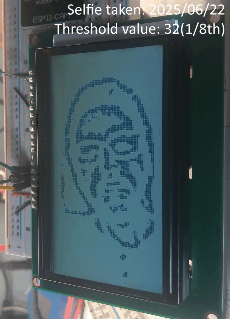
The threshold value is the point at which an edge is considered an edge; the lower the threshold – the more ‘edges’ are shown.
Values of 32 – 64 work well, higher values loose data (I would guess this is due to the information lost in pixel sub-sampling).
void setup() {
  Serial.begin(115200);
  psramInit();

  config.ledc_channel = LEDC_CHANNEL_0;
  config.ledc_timer = LEDC_TIMER_0;
  config.pin_d0 = Y2_GPIO_NUM;
  config.pin_d1 = Y3_GPIO_NUM;
  config.pin_d2 = Y4_GPIO_NUM;
  config.pin_d3 = Y5_GPIO_NUM;
  config.pin_d4 = Y6_GPIO_NUM;
  config.pin_d5 = Y7_GPIO_NUM;
  config.pin_d6 = Y8_GPIO_NUM;
  config.pin_d7 = Y9_GPIO_NUM;
  config.pin_xclk = XCLK_GPIO_NUM;
  config.pin_pclk = PCLK_GPIO_NUM;
  config.pin_vsync = VSYNC_GPIO_NUM;
  config.pin_href = HREF_GPIO_NUM;
  config.pin_sscb_sda = SIOD_GPIO_NUM;
  config.pin_sscb_scl = SIOC_GPIO_NUM;
  config.pin_pwdn = PWDN_GPIO_NUM;
  config.pin_reset = RESET_GPIO_NUM;
  config.xclk_freq_hz = 20000000;
  config.frame_size = FRAMESIZE_QVGA;
  config.pixel_format = PIXFORMAT_GRAYSCALE;
  config.grab_mode = CAMERA_GRAB_LATEST;
  config.fb_location = CAMERA_FB_IN_PSRAM;
  config.jpeg_quality = 12;
  config.fb_count = 2;

  esp_err_t err = esp_camera_init(&config);

  sensor_t * s = esp_camera_sensor_get();
  s->set_brightness(s, 0);     // -2 to 2
  s->set_contrast(s, 0);       // -2 to 2
  s->set_saturation(s, 0);     // -2 to 2
  s->set_special_effect(s, 0); // 0 to 6 (0 - No Effect, 1 - Negative, 2 - Grayscale, 3 - Red Tint, 4 - Green Tint, 5 - Blue Tint, 6 - Sepia)
  s->set_whitebal(s, 1);       // 0 = disable , 1 = enable
  s->set_awb_gain(s, 1);       // 0 = disable , 1 = enable
  s->set_wb_mode(s, 0);        // 0 to 4 - if awb_gain enabled
  s->set_exposure_ctrl(s, 1);  // 0 = disable , 1 = enable
  s->set_aec2(s, 0);           // 0 = disable , 1 = enable
  s->set_ae_level(s, 0);       // -2 to 2
  s->set_aec_value(s, 300);    // 0 to 1200
  s->set_gain_ctrl(s, 1);      // 0 = disable , 1 = enable
  s->set_agc_gain(s, 0);       // 0 to 30
  s->set_gainceiling(s, (gainceiling_t)0);  // 0 to 6
  s->set_bpc(s, 0);            // 0 = disable , 1 = enable
  s->set_wpc(s, 1);            // 0 = disable , 1 = enable
  s->set_raw_gma(s, 1);        // 0 = disable , 1 = enable
  s->set_lenc(s, 1);           // 0 = disable , 1 = enable
  s->set_hmirror(s, 0);        // 0 = disable , 1 = enable
  s->set_vflip(s, 0);          // 0 = disable , 1 = enable
  s->set_dcw(s, 1);            // 0 = disable , 1 = enable
  s->set_colorbar(s, 0);       // 0 = disable , 1 = enable

  u8g2.begin();
  u8g2.setDrawColor(1);

  u8g2.clearBuffer();
  u8g2.setFont(u8g2_font_ncenB08_tr);
  u8g2.drawStr(0, 10, "Loading...");
  u8g2.sendBuffer();

  delay(1000);
}
Setup ( )
This section starts up the serial monitor, initialises the PSRAM, camera and display.
The important camera configuration setting is: config.frame_size = FRAMESIZE_QVGA;
The display is programmed to show a ‘Loading…’ screen for 1 second to verify if the display is working.
void loop() {

  long startTime = millis();

  //PS ram allocations
  uint8_t *frame_buffer = (uint8_t *) ps_malloc(9792 * sizeof(uint8_t));
  uint8_t *gaus_buffer = (uint8_t *) ps_malloc(8976 * sizeof(uint8_t)); //holds output of gaus blur
  uint8_t *laplace_buffer = (uint8_t *) ps_malloc(8192 * sizeof(uint8_t));  //holds output of laplace edge detection

  u8g2.clearBuffer();
  camera_fb_t  * fb = NULL;
  fb = esp_camera_fb_get();
Start of the Loop ( )
The start allocates the necessary memory to the PSRAM, clears the display and camera buffers, then takes a photo.
  //320x240 pixel frame
  //window down to 272x144, centred
  //2x sub sample (every other pixel)
  //output is 136x72
  for (int f_y = 0; f_y < 72; f_y++) {
    for (int f_x = 0; f_x < 136; f_x++) {
      frame_buffer[(f_y * 136) + f_x] = fb->buf[(((f_y * 2) + 48) * 320) + ((f_x * 2) + 24)];  //subsample 2x2
      //frame_buffer[(f_y * 136) + f_x] = fb->buf[(((f_y) + 48) * 320) + ((f_x) + 24)];   //raw 136x72
      //    Serial.println(frame_buffer[(f_y * 136) + f_x]);
    }
  }
Pixel sub sampling
This section of code transfers the camera frame data from every other pixel in to a specific 136x72pixel frame buffer.
  //5x5 gaussian blur
  //  1  4  6  4  1
  //  4 16 24 16  4
  //  6 24 36 24  6  * 1/256
  //  4 16 24 16  4
  //  1  4  6  4  1
  //convoluted over frame buffer
  //no padding
  //output is 132x68
  for (int g_y = 0; g_y < 68; g_y++) {
    for (int g_x = 0; g_x < 132; g_x++) {
      int frameBufNo = (((g_y + 2) * 136) + (g_x + 2));  //
      int gausSubTotal = 0;

      gausSubTotal += frame_buffer[frameBufNo - 274]; // * 1
      gausSubTotal += frame_buffer[frameBufNo - 273] * 4;
      gausSubTotal += frame_buffer[frameBufNo - 272] * 6;
      gausSubTotal += frame_buffer[frameBufNo - 271] * 4;
      gausSubTotal += frame_buffer[frameBufNo - 270]; // * 1

      gausSubTotal += frame_buffer[frameBufNo - 138] * 4;
      gausSubTotal += frame_buffer[frameBufNo - 137] * 16;
      gausSubTotal += frame_buffer[frameBufNo - 136] * 24;
      gausSubTotal += frame_buffer[frameBufNo - 135] * 16;
      gausSubTotal += frame_buffer[frameBufNo - 134] * 4;

      gausSubTotal += frame_buffer[frameBufNo - 2] * 6;
      gausSubTotal += frame_buffer[frameBufNo - 1] * 24;
      gausSubTotal += frame_buffer[frameBufNo] * 36;
      gausSubTotal += frame_buffer[frameBufNo + 1] * 24;
      gausSubTotal += frame_buffer[frameBufNo + 2] * 6;

      gausSubTotal += frame_buffer[frameBufNo + 134] * 4;
      gausSubTotal += frame_buffer[frameBufNo + 135] * 16;
      gausSubTotal += frame_buffer[frameBufNo + 136] * 24;
      gausSubTotal += frame_buffer[frameBufNo + 137] * 16;
      gausSubTotal += frame_buffer[frameBufNo + 138] * 4;

      gausSubTotal += frame_buffer[frameBufNo + 270]; // * 1
      gausSubTotal += frame_buffer[frameBufNo + 271] * 4;
      gausSubTotal += frame_buffer[frameBufNo + 272] * 6;
      gausSubTotal += frame_buffer[frameBufNo + 273] * 4;
      gausSubTotal += frame_buffer[frameBufNo + 274]; // * 1

      int gausBufNo = ((g_y * 132) + g_x);
      //divide by 256 is same as bit shift by 8 places (2^8 = 256)
      gaus_buffer[gausBufNo] = gausSubTotal >> 8;
    }
  }
Gaussian Blur
This convolutes a 5×5 Gaussian blur kernel over the frame data to give a 132×68 blurred image.
At the end the, the relevant element in the gaus_buffer is calculated and the output saved there.
  //5x5 laplace filter
  // -1 -1 -1 -1 -1
  // -1 -1 -1 -1 -1
  // -1 -1 24 -1 -1
  // -1 -1 -1 -1 -1
  // -1 -1 -1 -1 -1
  //convoluted over gaus buffer
  //no padding
  //output is 128x64
  //onboard thresholding and export
  for (int l_y = 0; l_y < 64; l_y++) {
    for (int l_x = 0; l_x < 128; l_x++) {
      int laplaceSubTotal = 0;

      int gausBufTrans = (((l_y + 2) * 132) + (l_x + 2));

      laplaceSubTotal += -gaus_buffer[gausBufTrans - 266];
      laplaceSubTotal += -gaus_buffer[gausBufTrans - 265];
      laplaceSubTotal += -gaus_buffer[gausBufTrans - 264];
      laplaceSubTotal += -gaus_buffer[gausBufTrans - 263];
      laplaceSubTotal += -gaus_buffer[gausBufTrans - 262];

      laplaceSubTotal += -gaus_buffer[gausBufTrans - 134];
      laplaceSubTotal += -gaus_buffer[gausBufTrans - 133];
      laplaceSubTotal += -gaus_buffer[gausBufTrans - 132];
      laplaceSubTotal += -gaus_buffer[gausBufTrans - 131];
      laplaceSubTotal += -gaus_buffer[gausBufTrans - 130];

      laplaceSubTotal += -gaus_buffer[gausBufTrans - 2];
      laplaceSubTotal += -gaus_buffer[gausBufTrans - 1];
      laplaceSubTotal += gaus_buffer[gausBufTrans] * 24;
      laplaceSubTotal += -gaus_buffer[gausBufTrans + 1];
      laplaceSubTotal += -gaus_buffer[gausBufTrans + 2];

      laplaceSubTotal += -gaus_buffer[gausBufTrans + 130];
      laplaceSubTotal += -gaus_buffer[gausBufTrans + 131];
      laplaceSubTotal += -gaus_buffer[gausBufTrans + 132];
      laplaceSubTotal += -gaus_buffer[gausBufTrans + 133];
      laplaceSubTotal += -gaus_buffer[gausBufTrans + 134];

      laplaceSubTotal += -gaus_buffer[gausBufTrans + 262];
      laplaceSubTotal += -gaus_buffer[gausBufTrans + 263];
      laplaceSubTotal += -gaus_buffer[gausBufTrans + 264];
      laplaceSubTotal += -gaus_buffer[gausBufTrans + 265];
      laplaceSubTotal += -gaus_buffer[gausBufTrans + 266];

      if (laplaceSubTotal > thresholdValue) {
        u8g2.drawPixel(l_x, l_y);
      }

    }
  }
Laplacian Edge Detection & Image Rendering
A 5×5 Laplacian edge detection kernel is convoluted over the Gaussian frame.
The output of the kernel is checked against the threshold value; and drawn to the relevant pixel if it exceeds.
  u8g2.sendBuffer();
  esp_camera_fb_return(fb);   //return the frame buffer
  free(frame_buffer);
  free(gaus_buffer);
  free(laplace_buffer);

  long frameTime = millis() - startTime;
  Serial.println(frameTime);

}
End of the Loop ( )
This final part commits the completed buffer to the display and frees up all of the memory used.
There is the potential to use pixel binning, or pooling, instead of sub-sampling to get the desired resolution, but like the electron I am, I took the path of least resistance.