
Curiosity is a strong driving force; especially, when there is a note on the datasheet regarding braking and PWM control. You can see the note under the truth table on the how-to guide here for the DRV8871. Also, the idea of having a closed loop motor able to deliver about 2.7kg.cm of torque and 300RPM speed is appealing.
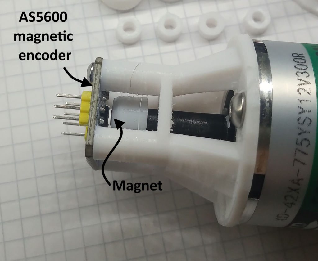
The AS5600 rotary encoder was employed for positional feedback – bit overkill given the 12-bit resolution. There is also another how-to guide here for interfacing the AS5600 here.
A test rig was constructed with PLA, extruded from a 3D printer, and consists of two parts:
- The “nubbin” which connects the motor spindle to the magnet.
- The “cage” that spaces the magnetic end of the nubbin a suitable distance away from the sensor.
Test 1: Braking
The data sheet notes that when both inputs go high, the output goes to ‘brake’, while if both inputs go low then the output goes to ‘coast’. So the first test is to see if there is a difference, and if so, is there much of an affect.
The program spins the motor up to speed* and then at 3000ms the brake is applied. After 4500ms, the test is halted. All data is output to the serial monitor with the time in millis( );
The code is provided for full transparency.
*data suggests that the motor gets to full speed in about 1 to 1.3 seconds.
#include <Wire.h>
#include "AS5600.h"

AS5600 as5600;

const int IN1 = 5;
const int IN2 = 6;
long totalTimeElapsed = 0;

void setup() {
  Serial.begin(115200);
  Wire.begin();
  as5600.begin(4);  //set direction pin.
  as5600.setDirection(AS5600_CLOCK_WISE);
  as5600.resetCumulativePosition();
  pinMode(IN1, OUTPUT);
  pinMode(IN2, OUTPUT);
  digitalWrite(IN1, LOW);
  digitalWrite(IN2, LOW);
  Serial.println("time,  rotational speed");
  delay(500);
}

void loop() {
  //break test
   do {
      totalTimeElapsed = millis();
      digitalWrite(IN1, HIGH);
      digitalWrite(IN2, LOW);
      Serial.print(millis());
      Serial.print(",  ");
      Serial.println(as5600.getCumulativePosition());
    } while (totalTimeElapsed < 3000);
    digitalWrite(IN1, HIGH);  //change to LOW for coast
    digitalWrite(IN2, HIGH);  //change to LOW for coast
    do {
      totalTimeElapsed = millis();
      Serial.print(millis());
      Serial.print(",  ");
      Serial.println(as5600.getCumulativePosition());
    } while (totalTimeElapsed < 4500);
  while (1);
}
Due to noise, the graph below shows a 15-point moving average of the two runs. The point the “brakes” are applied at 3000ms has been shown in green. I believe the prior oscillations to be due to a slightly eccentric magnet placement.
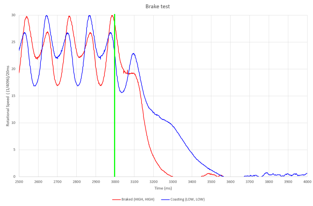
The outcome from this is clear to see. The motor comes to a complete standstill nearly 300ms sooner when set to “brake”. This is a significant difference of nearly 100% in time. Again, for honesty, the sample size here is n=1 per series.
This test rig does not allow for a loaded test – this would be interesting to test in the future.
Test 2: PWM Speed Control
The datasheet makes note that it’s better to switch between braking and driving; opposed to driving from a ‘coasting’ position. This test is designed to measure that by looping through the PWM range (0-255), pausing at each point for 50ms to take and send a reading.
The setup for the code is identical to above, so this is the pertinent loop.
void loop() {
  for (int i = 0; i < 256; i++) {
    totalTimeElapsed = millis();
    digitalWrite(IN1, HIGH);
    analogWrite(IN2, 255 - i);
    Serial.print(millis());
    Serial.print(",  ");
    Serial.print(i);
    Serial.print(",  ");
    Serial.println(as5600.getCumulativePosition());
    delay(50);
  }
  digitalWrite(IN1, LOW);
  digitalWrite(IN2, LOW);
  while (1);
}
The results from this have been graphed below. Again, this is a 15-point moving average to filter noise. Please note the colours do not match the previous graph.
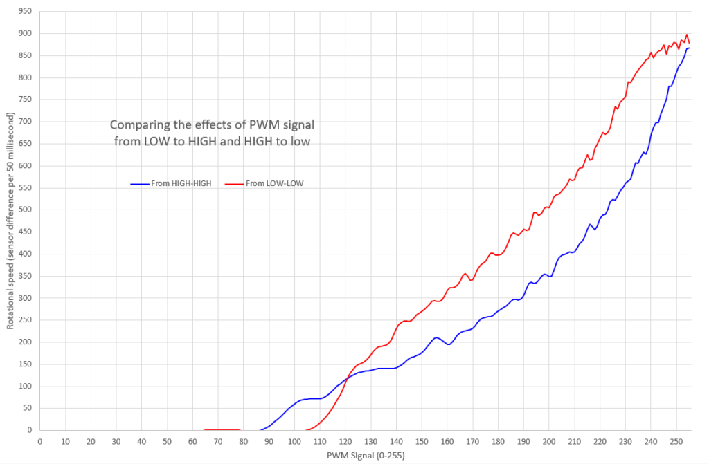
From this, we can see that the datasheet is correct: controlling the motor from a braked position gives a sooner response and therefore a wider band of operation (additional 12%).
Conclusion
These tests have verified the claims made from the datasheet. It would be interesting to add a mass/load to the motor, to see if the performance difference is exacerbated at all. If there are any tests you’re interested in; let me know.