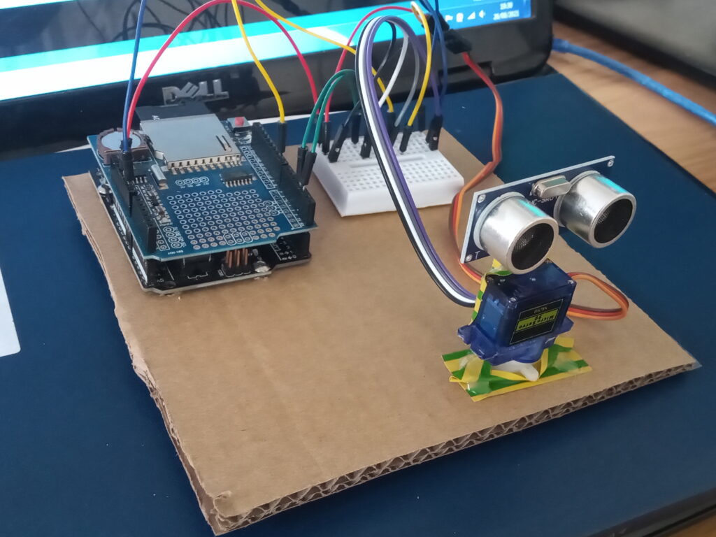
Borne from sheer curiosity; this project started in August 2021 with an Arduino Starter kit, and evolved through multiple iterations before becoming my final project in college in 2025. The final scanner is equipped with a Garmin LiDAR-LiTE sensor, and is capable of accurately mapping internal spaces and exporting the data to an .xyz point cloud.
Due to the longevity of this project, previous versions of the scanner from 2021 and 2023 have been documented on this webpage. Progress through the years has not been linear, and has spawned a number of side projects, including a 3D object scanner built from an Ender 3 printer, and a method of creating a coloured depth-map “photo” and displaying on a TFT screen.
Overview
Having a 3D scanner would be useful in my day job; it’s not uncommon to have the requirement to measure vast internal spaces quickly and accurately. At the moment, that need is met by a manual laser distance finder, a tape measure and some wild assumptions.
Building on the experienced gained from building the previous 3D scanner, the bottleneck was discovered to be the simple fact that a single scan is prone to “shadows” where objects in the foreground block everything behind it.
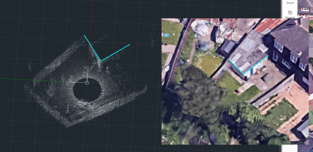
This new scanner aims to eliminate that problem by completing multiple scans in a single point cloud by self-locating using backsights/foresights; much like a surveyors total station, but with the ability to a 3D scan.
One of the unique features of this scanner that provides an advantage over a typical total station is the toroid shape of the design, allowing for a true vertical measurement, rather than relying on a secondary measurement and manual input of data.
To be honest, I’ve been hankering to do this project for a while, a “version 2” was mooted on a now hidden page from 2023, but it took the a college assignment to provide the impetus to actually pull the trigger.
Motion Systems
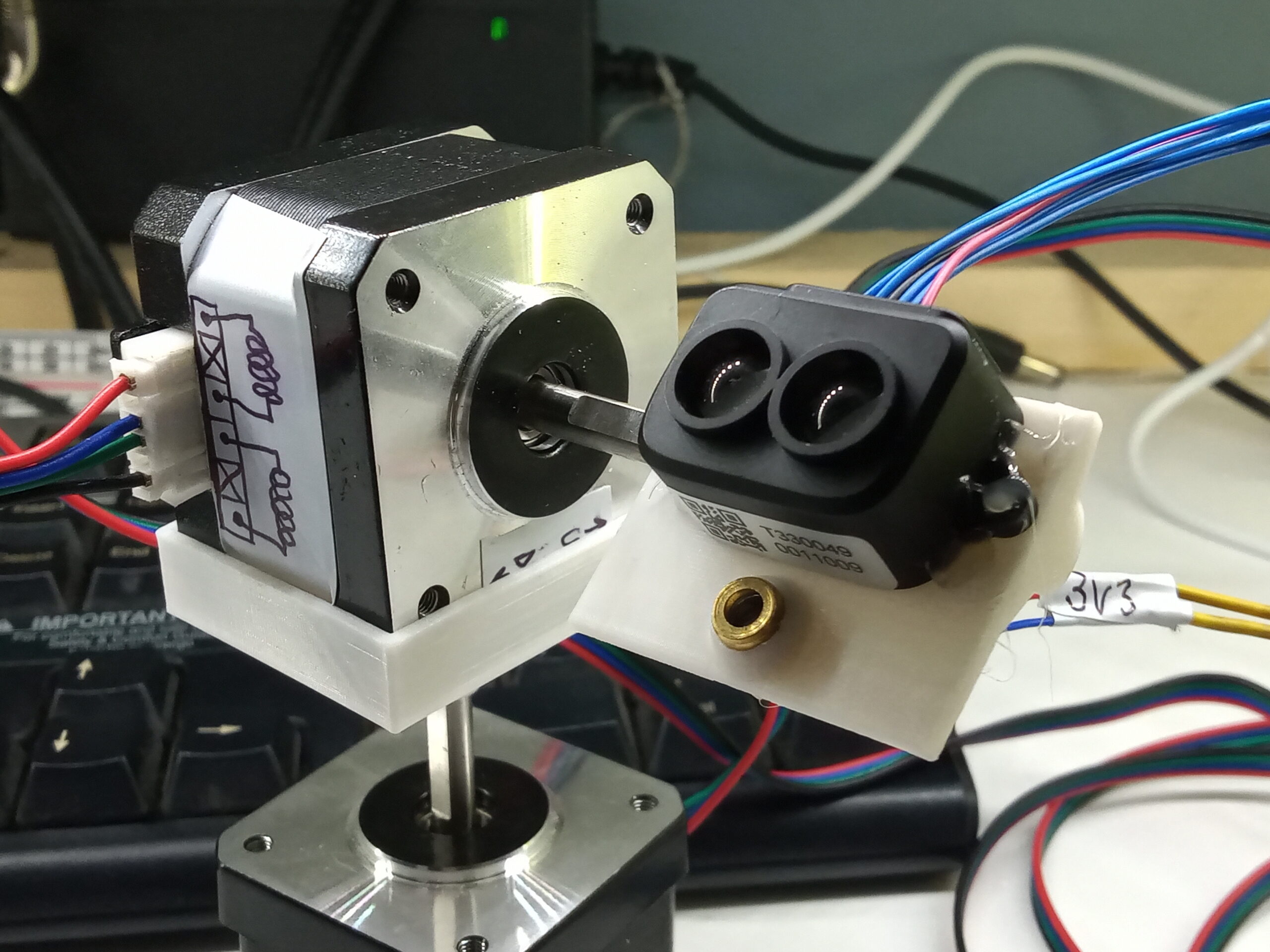
As previous, a pair of NEMA17 stepper motors were used to control the altitude and azimuth, these were driven a pair of A4988 drivers. I know “better” drivers exist, and I even have a pair of DRV8825’s kicking around, but now was not the time for change.
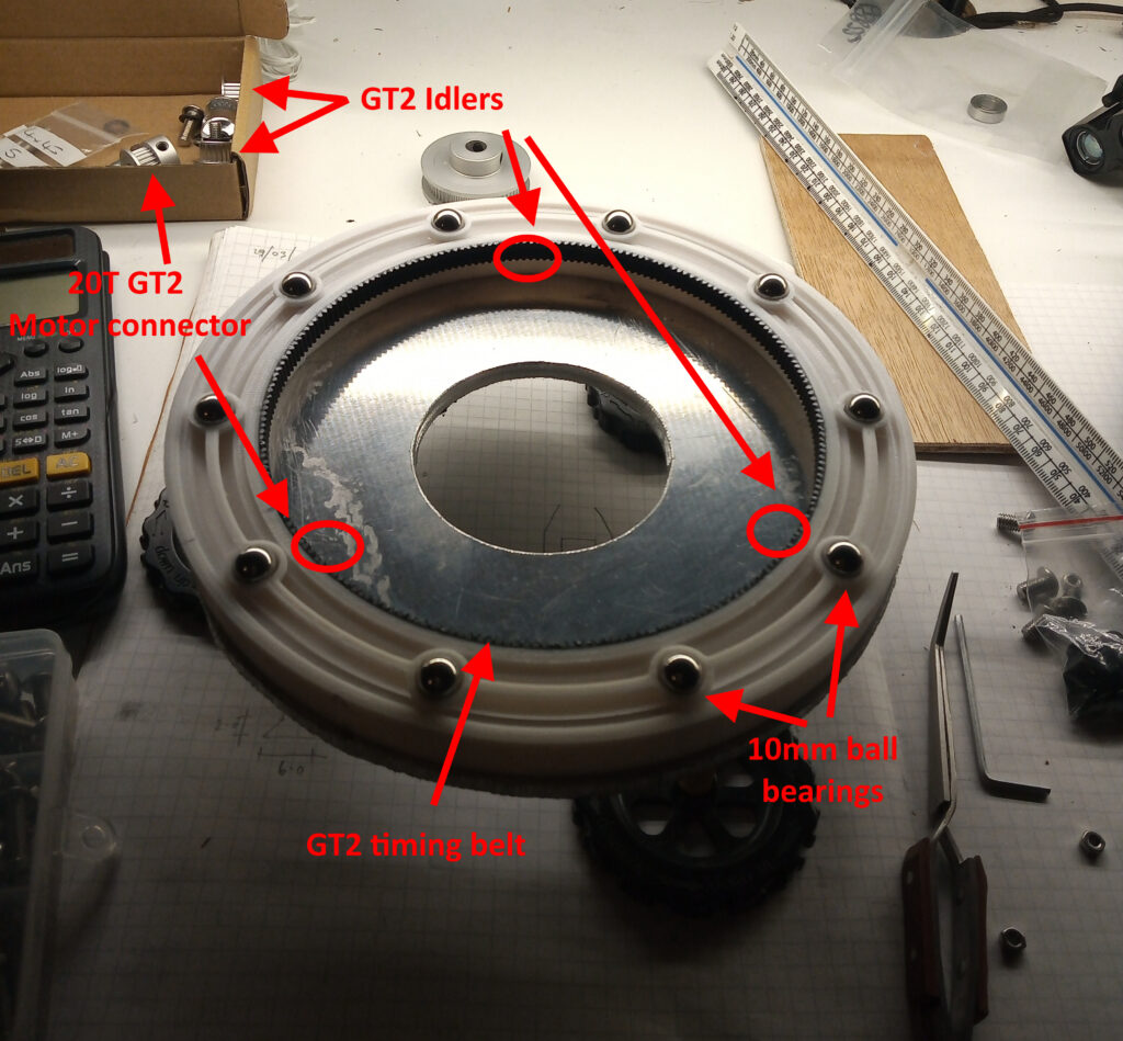
A slip ring was used to allow full a 360o rotation of the head without the sensor garrotting itself with it’s own wires. As such, a pully setup was chosen using GT2 timing belt with another 20T pully on the motor and a 60T pully on the scan head to give a gear ratio of 1:3.

The upper part of the scanner is sat on a turntable which has a ring gear fabricated from GT2 timing belt, and the upper part is rotated in a circle by a 20-tooth GT2 pully connected to the azimuth stepper motor. This gives a gear reduction of 1:10.7 (20:214), so can either allow for greater resolution or reduced error from micro-step drift as discovered here [reddit post].
To ensure that the two halves of the scanner didn’t come apart; two additional idler pullies were fitted at 120o angles. The flanges from the pullies allow the scanner to be held from the top half, however, this is not advisable.
Electronics
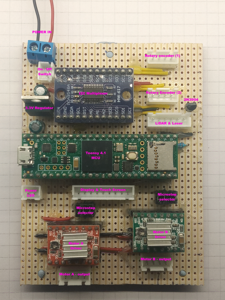
A Teensy 4.1 microcontroller is the main brains of the scanner, featuring a 600MHz processor with floating point unit, onboard SD card, and plenty of memory for handling the graphic user interface.
The LiDAR sensor thatdoes the distance measurements is a Garmin LiDAR-Lite v3hp which is claimed to have a range of 40m ±1cm, a o a beam divergence of about 0.5o and a rate of 1kHz.
The angular sensors are a pair of AS5600 magnetic rotary encoders giving a 12-bit angular resolution (4096 segments of a complete circle). As the encoders have the same I2C address hard-coded they are therefore fed in to PCA9548A 8-channel I2C multiplexer.
Attached to the head is a red laser diode is to provide a target marker; the operation of this is controlled by a 2N3904 NPN BJT transistor activated by the microcontroller.
Power is from an 11.1V 3S LiPo battery. The intial 6000mAH power pack was too large for the final model, so a pair 2200mAH 3S LiPo batteries were selected. The 3.3V linear voltage regulator seen on the photo had overheating problems, so it was swapped out for a buck converter.
Operation and User Interface
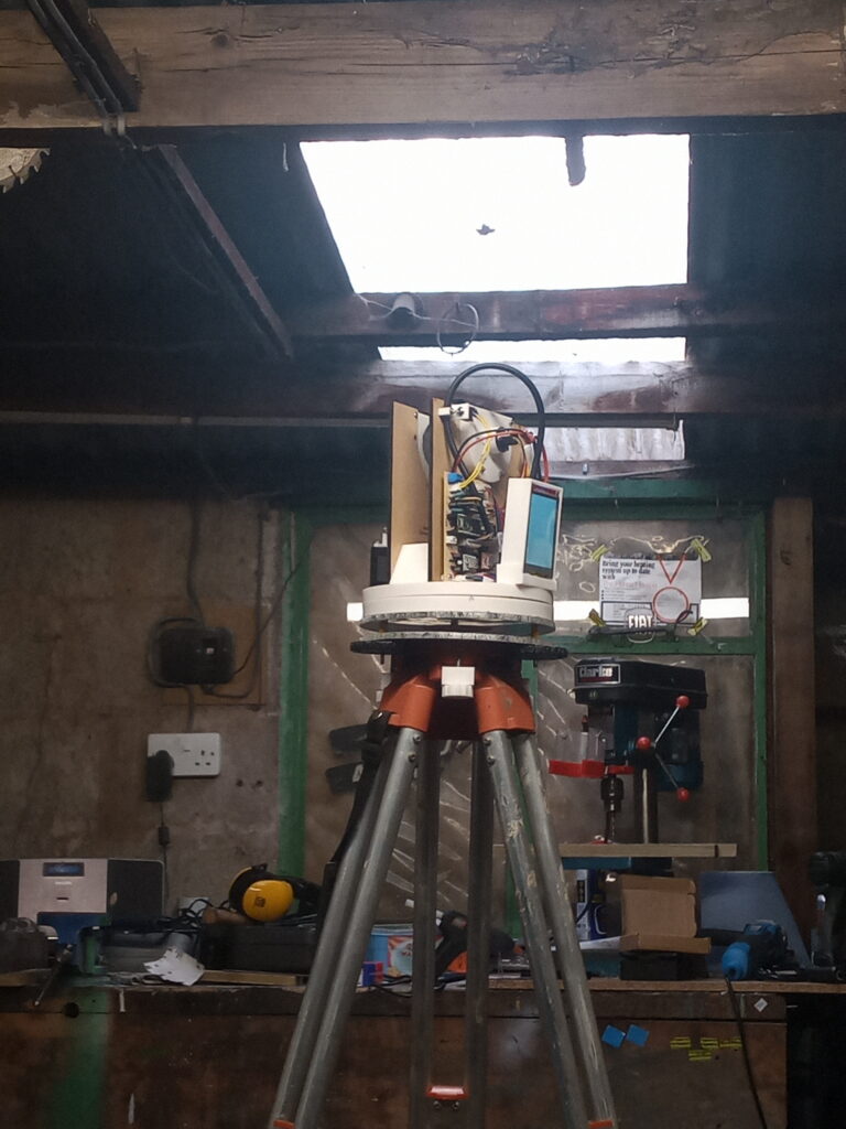
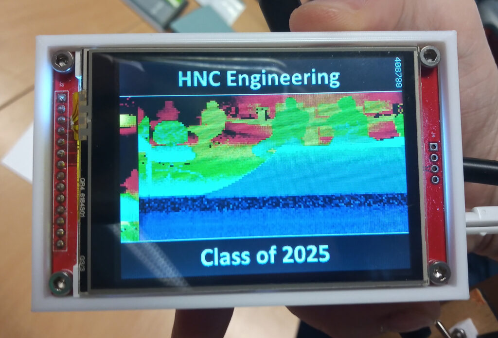
The scanner is operated via a touch screen console consisting of a 3.2inch ILI9341 TFT display with a resolution of 320×240 pixels (QVGA), and an XPT2046 resistive touch sensor.
When the user turns on the scanner via the toggle switch, an initial menu is displayed offering the user to move the scanner, set the home position, start a scan or take a “photo”!
“Photo” mode is colour coded depth map conducted over a set area, where points far away are shown as red, and points closer are shown as blue.
Chassis Construction.
This entire project was built using hobby-grade DIY tools and off-the-shelf components.
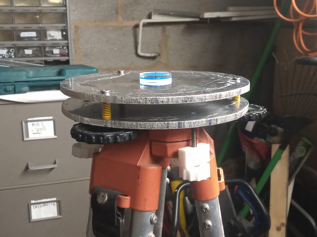
The aluminium levelling bed was butchered together with a hacksaw and a set of bed levelling springs from a 3D printer. This lower section of the bed is clamped to a standard surveyors tripod, while the upper section is affixed to the body.
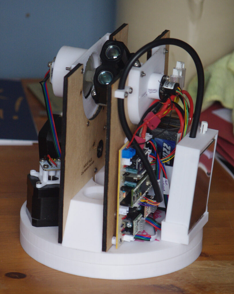
The body is split in to two sections to allow rotation; the lower section is formed with 3D printed parts. Attached to this are two plywood spines where the head is clamped between with more 3D printed parts.
Results, Conclusion & Future Plans
The proof of the pudding is in the eating…
…and this pudding tastes undercooked: the entire project was completed in 32 weeks, working only during the evenings and weekends with a team consisting one person.
While the accuracy was tested to be within a 0.16% margin of error, the range of the LiDAR sensor was severely under achieving; struggling to achieve 50% of it’s claimed specification. The time taken to complete a single scan can range from 7 minutes for a 7.3k point scan to 14 minutes for a 14.4k point scan.
Quite honestly, the results far were far below expectations and rather disheartening, especially given the amount of time and effort dedicated. This is the reason why the scanner has been collecting dust under my desk for nearly a whole year and it’s taken this long to do a write-up.
In regards to future plans, I hope to one day pick this back up again. There are a number of improvements to be made such as increasing range and decreasing the scan time, as well as implementing the multi-scan feature.
If you’re interested, then you can read the entire 90 page report that was submitted for my qualification here.
Page created: 15/05/2026
Last updated: 23/05/2026