The VL6180X is a time-of-flight distance sensor from 0-100mm with millimetre accuracy. As with every sensor there are some pros and cons; as listed below:
Pros
- Millimetre accuracy
- Relatively cheap (<£10)
- Has a bigger sister (VL53L0X) which can measure from 30-1,000mm
- Simple to wire and easy to program
Cons
- Not precise – the beam divergance is rather wide
- Fairly noisy output
I’ve had accurate measurements up to 200mm. Distances above 200mm just outputs 255mm – I don’t think it’s a coincidence that 255 = (28)-1 and this is an 8 bit sensor.
The sensor also has an ambient light sensor and many other features that I’ve not explored. More information is available on the datasheet.
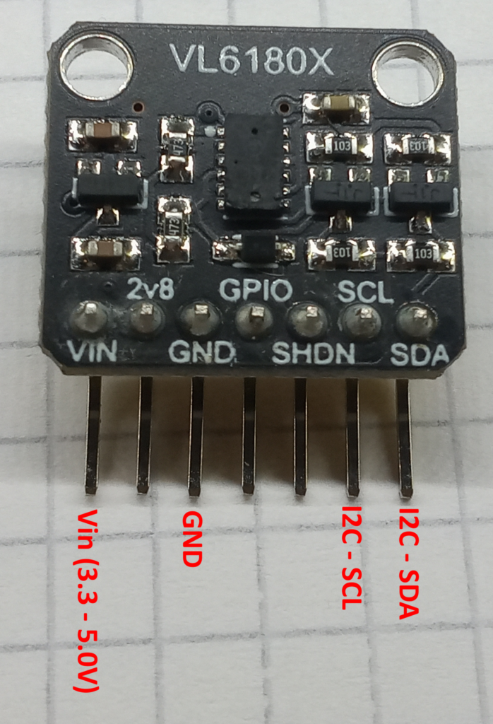
Pinout
There are 7 pins on this module but you only need to connect 4 of them to get the sensor working.
- VIN = +Voltage supply (2.8V – 5.0V)
- GND = Ground. Simple
- SCL = I2C clock
- SDA = I2C data
The I2C pins will vary depending on your MCU as detailed in the table below.
| MCU | I2C-SDA | I2C-SCL |
| Arduino Uno | A4 | A5 |
| Arduino Nano | A4 | A5 |
| Arduino Mega | D20 | D21 |
| ESP32 | GPIO 21 | GPIO 22 |
Code
There is a library by Pololu called ‘VL6180X’ which handles the I2C communications in a succinct and efficient manner.
Inside the library is an example sketch called ‘RangeSingleShot’, as detailed below. Upload this sketch, open the serial monitor and watch the numbers roll in! Simple!
#include <Wire.h>
#include <VL6180X.h>

VL6180X sensor;

void setup()
{
  Serial.begin(9600);
  Wire.begin();

  sensor.init();
  sensor.configureDefault();
  sensor.setTimeout(500);
}

void loop()
{
  Serial.print(sensor.readRangeSingleMillimeters());
  if (sensor.timeoutOccurred()) {
    Serial.print(" TIMEOUT");
  }
  Serial.println();
}
Beam Divergence
This sensor was purchased to use with the Ender 3-D scanner – on paper, it was fast, easy to use and had millimetre accuracy. Unfortunately every scan looked like a peanut.
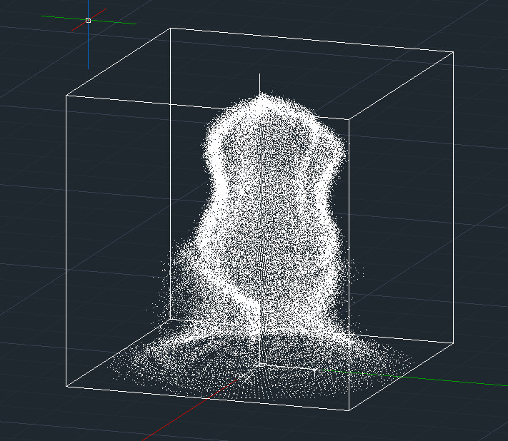
The emitting laser has a beam divergence of 25 degrees, therefore while the sensor is accurate; it is far from precise. This divergence causes the ‘peanut’ effect by rounding all the sharp arrises.
Test Setup
An experiment was set up to measure the effects of beam divergence by moving a reflective target perpendicular in front of an unreflective background. Readings were taken by pressing a button which would then output the mean average of 50 measurements to mitigate the effects of the noise.
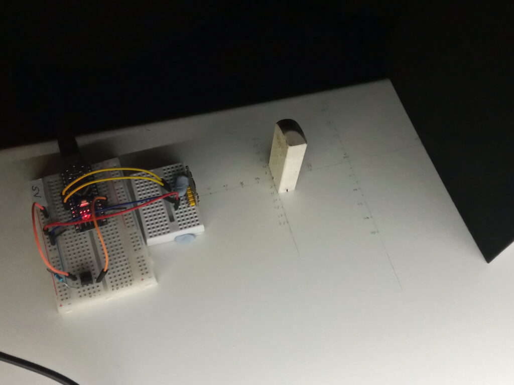
Before each test, a sheet of white card was placed at the perpendicular line to obtain a ‘control’ measurement. This is shown as a straight grey line on the graphs below.
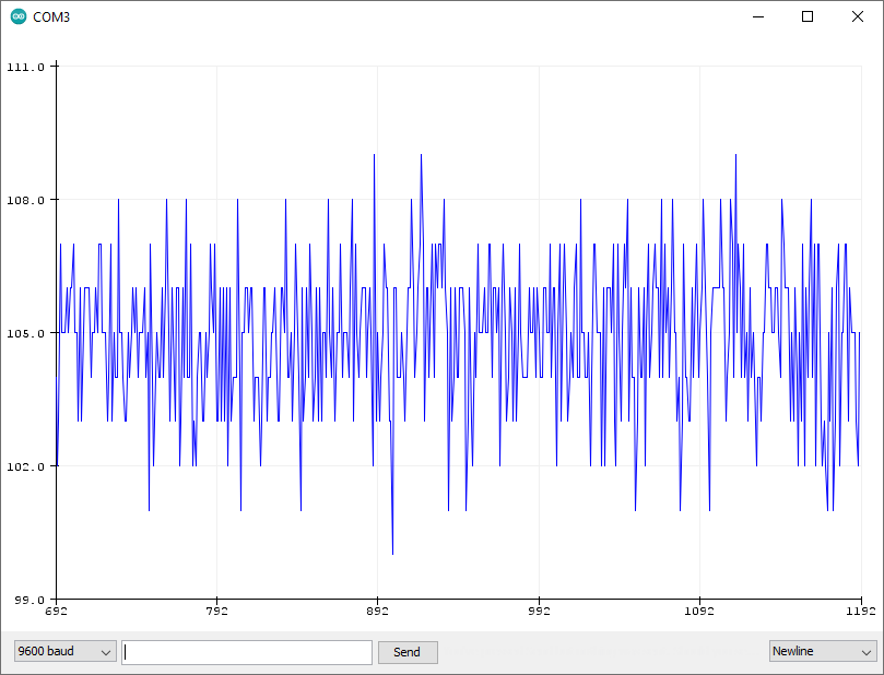
Test results
The reflective target (in this case a pencil eraser) was moved across the sensor, first bearing it’s wide face (22mm) and then bearing it’s narrow face (11mm). Measurements were recorded at 5mm intervals.
The blue lines on the graph show the results when the wide facet was facing the the target. The orange lines show the results when the narrow facet was facing the target. The corresponding coloured boxes show the ‘ideal’ shape if there was zero beam divergence.
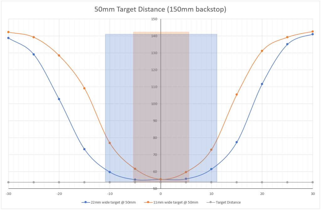
These lovely curved lines really explain the ‘peanut’ shape to everything. The sensor begins to detect the target even when it’s not directly in front. The 11mm wide target begins to be detected when the edge of the eraser is 20mm from the centre line of the sensor.
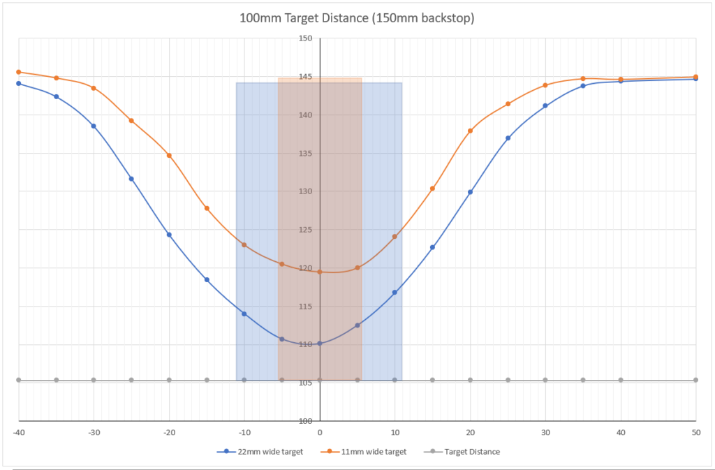
It’s also interesting to note that at 100mm, the measurements failed to reach the control measurement. According to these results, the wide target only reached 95% of the control, while the narrow target was only ever 85%!
Comparison to Other Sensors
At this moment in time, you only have my word that the above results are poor. So, here are some comparable graphs using the TF Luna LiDAR sensor and Sharp 0A51SK IR sensor.
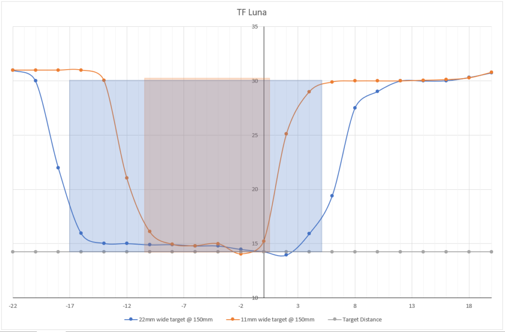
The above graph shows nice steep lines at the edges of the target; the overall shape of the graph is much closer to the shape of the boxes.
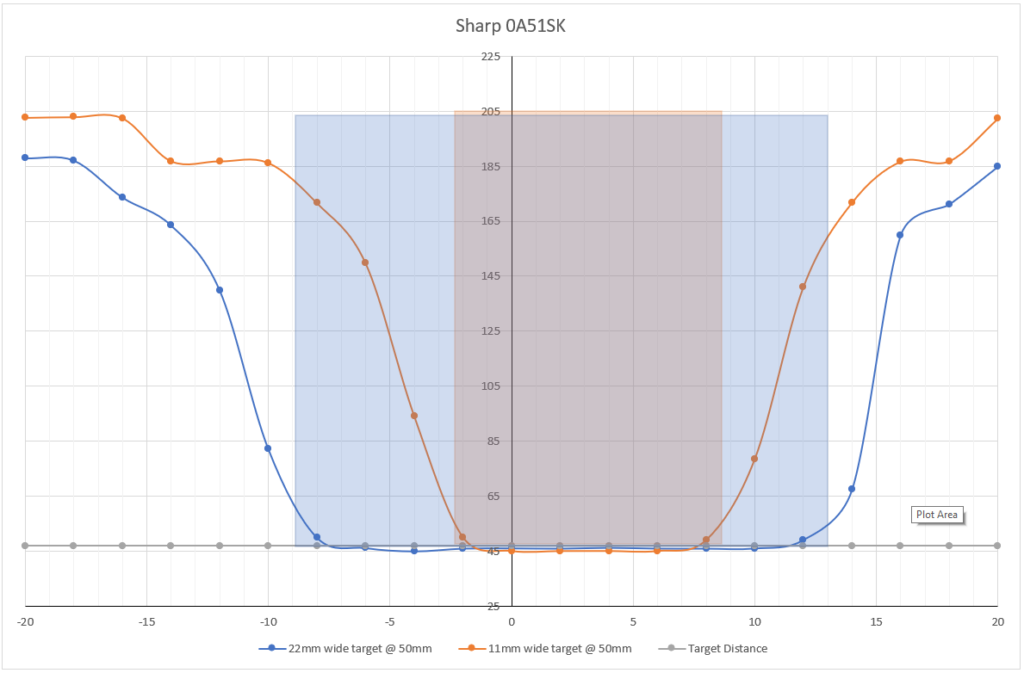
The Sharp IR sensor is not as good as the TF Luna, but still more precise than the VL6180X.
Conclusion
This sensor is generally competent, especially for the price. But it’s not without fault. It excels in one dimensional applications, such as ball-on-beam balancing robot.
It might be possible to add a lens or blinkers to the emitter to reduce the beam divergence, but as the chip measures less than 3x5mm, any external modification would me miniscule.
Last updated: 19/01/2023