Using SMD Resistors on Vero/Strip Board

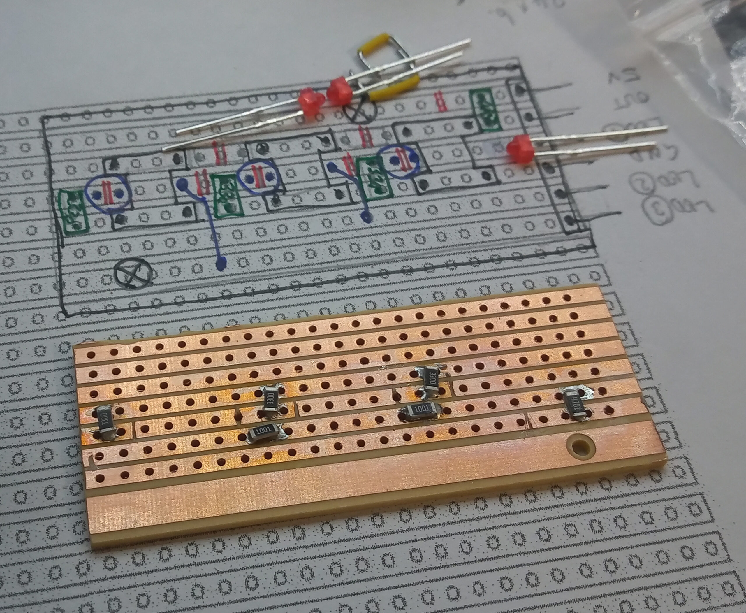
When prototyping, my preferred protoboard is Verobaord/Stripboard as it has handy 2mm wide copper busses set at a 2.54mm (0.1inch) pitch.

As a result, there are a few sizes of SMD/SMT components that fit nicely:

  • 1206 (metric 3216) and 1210 (metric 3225) are good for jumping to the adjacent bus.
  • 1206 (metric 3216) are good for jumps over breaks. The 1210 is a bit too wide.
  • 2010 (metric 5024) are able to jump two busses.
Original image courtesy of: Resistor Packing Specification DIP SMD Resistor Sizes and Packages【Synton-Tech】

The image shows how the various sized components can be positioned on the veroboard / stripboard.

In order to create a new user-interface panel for the bark blind, the below board uses six 1206/3216 size SMD/SMT resistors, along with through-hole components.

There are three 330 ohm resistors for the 1.8mm LEDs, and a resistor network comprised of a 4K7 and two 1K ohm resistors. The resistor network allows all three buttons to be interfaced with a single pin.

My process was as follows:

  • Cut the board to size and also cut all the breaks in any of the copper traces. I used a fresh Stanley knife and a steady hand.
  • Test with a multimeter.
  • Wet the copper traces with solder where the pads of the SMD components are to sit.
  • Then wick away most of the solder. The components should sit flat.
  • Apply a small amount of solder flux paste on the ‘pads’.
  • Place the SMD components. The flux paste should help keep the component in place.
  • Use a hot air gun to then reflow the components to the solder pads. I used 400 oC temperature, 3/8ths air flow and a narrow nozzle (circa 4mm).
  • Test the components with a multimeter.
  • There was an instance where I had to add some solder; so I placed it against the joint and used the hot air station to melt the solder in to the joint.
  • Then it was a case of doing the rest of the through hole components.

Overall, I’m really happy with the outcome. The initial design was a bit of a head-scratcher and the soldering was a bit more challenging, but it fully worked first time and was stable than than the breadboarded version.

I’m aware that the next step is for PCB design & manufacture. I would like to experiment with home-brew-PCBs by using the SLA 3D printer to expose photoresist FR2 copper clad board.

One step at a time.