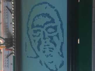
An Exercise in Futility: Edge detection on a ST7920 128×64 LCD display
Ever since doing the successful real-time edge detection experiment using the GC9A01 display, I couldn’t help but wonder what it would be like on the […]
Ever since doing the successful real-time edge detection experiment using the GC9A01 display, I couldn’t help but wonder what it would be like on the […]
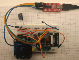
After finding myself with a little extra time over the festive period, I decided to go back over the ESP32-CAM homebrew computer vision project after […]
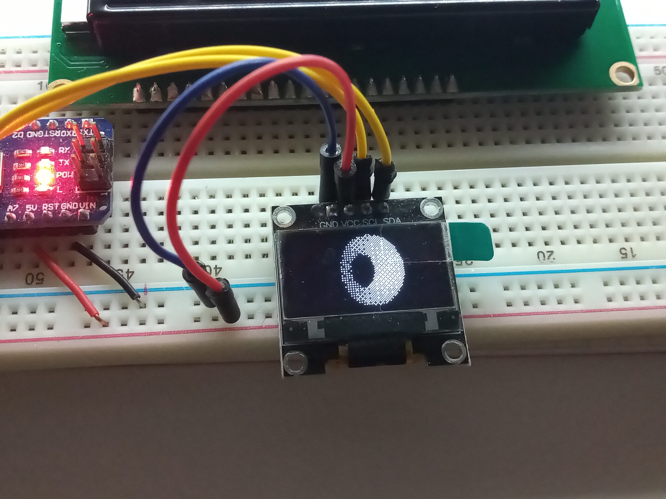
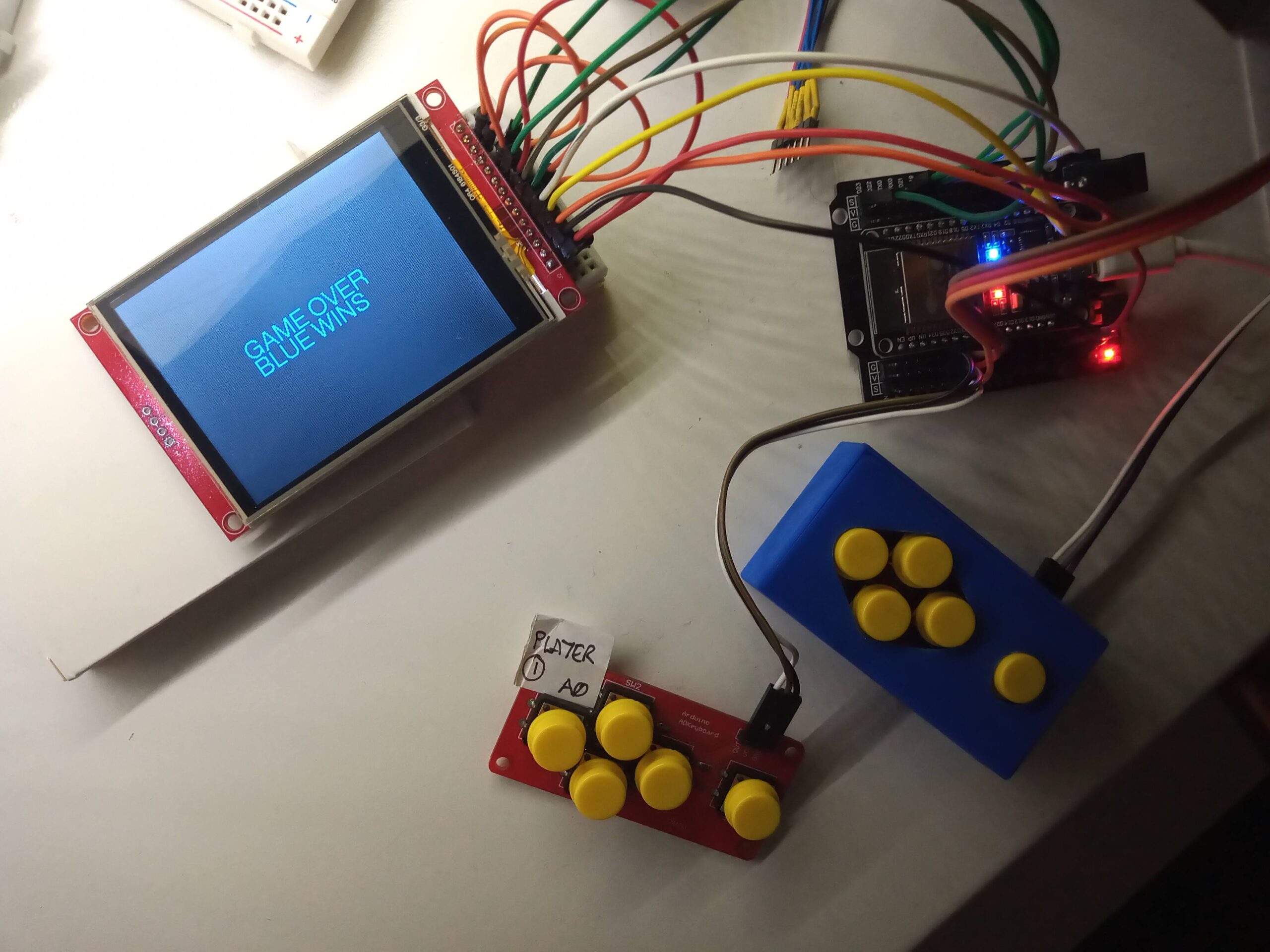
This started as the result of misreading the title of a Reddit post by u/Trotztd and lead to rendering 3D graphics on an Arduino. The […]
Sometimes the best way to learn a new thing is to use it in a new project. This little project was a short and successful […]
Work begets work. For example; if you send an email, you’ll likely get a reply which needs actioning. Or, if you finish your work early […]
Instead of concentrating on the proper projects, I’ve devoted my time to literature, recycling and wood working as detailed below. Taking procrastination to a new […]
Apparently I get distracted easily. This was another project that reached 85% and then sat idle for several months. Here is a write up documenting […]
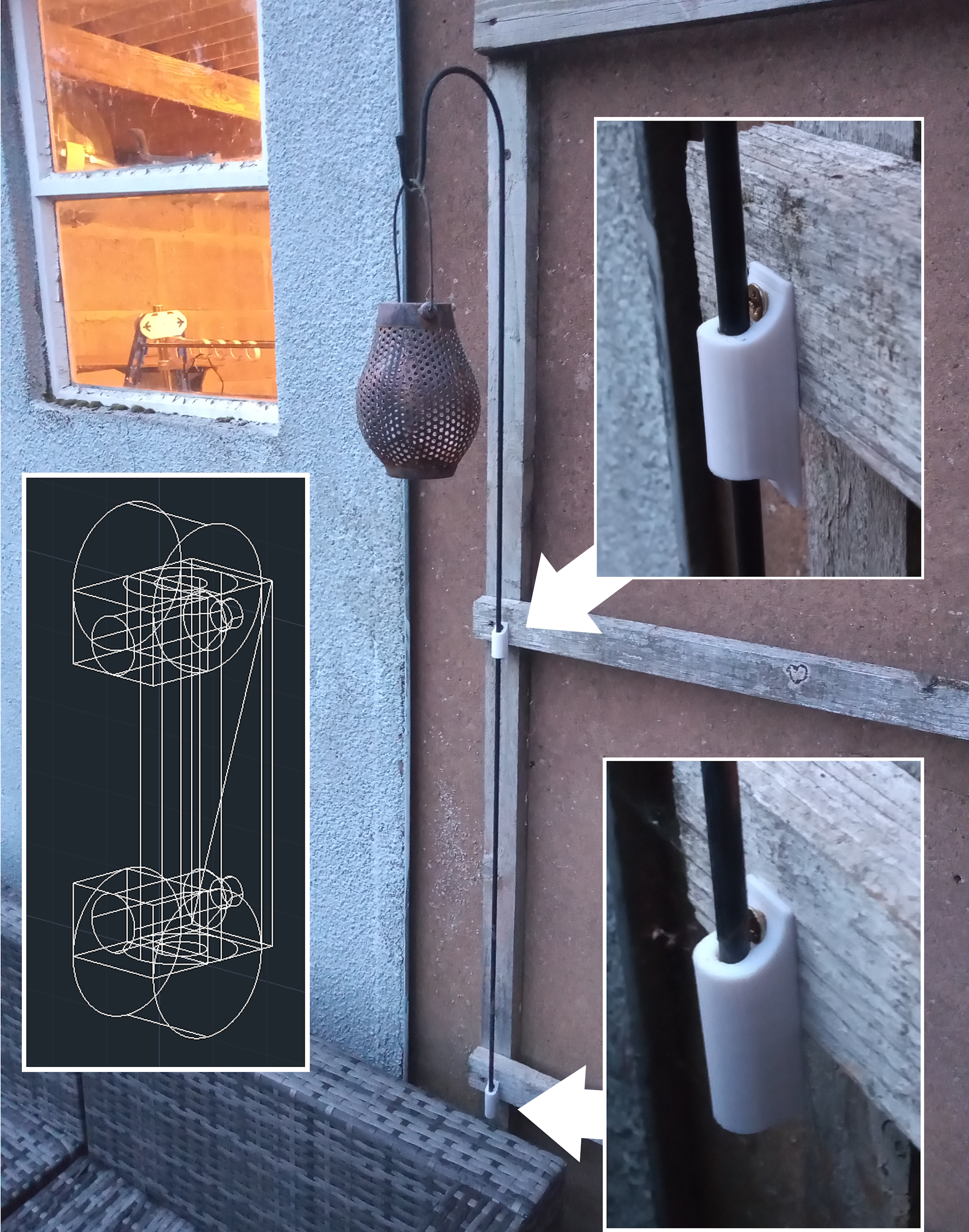
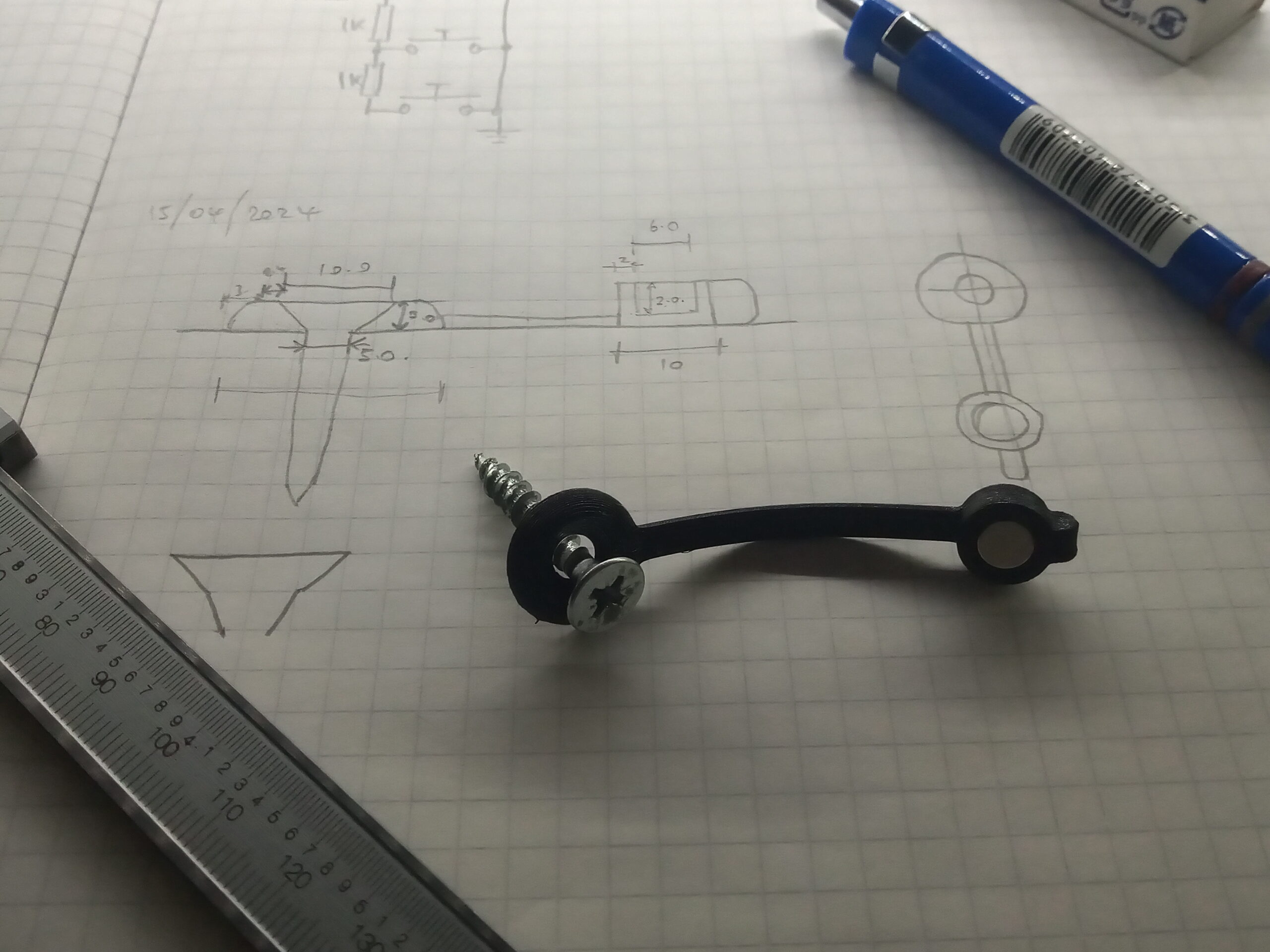
Due to the acquisition of new patio furniture; we needed to move the ground mounted light spike. Cue 3D printing a pair of holders to […]
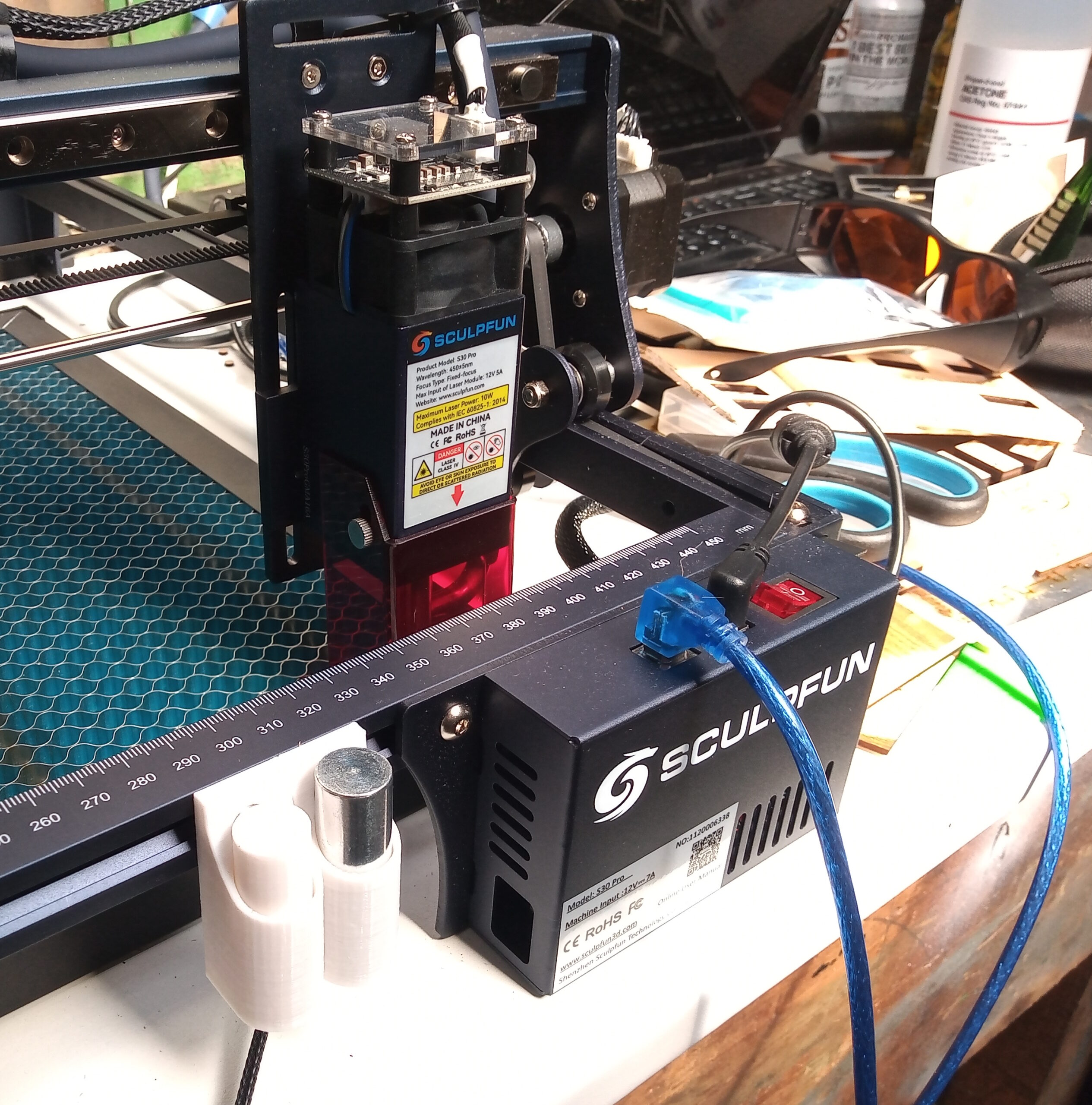
After much deliberation over many months, the workshop has now been upgraded with a Sculpfun S30 Pro laser cutter/engraver. This particular model features a 10W […]
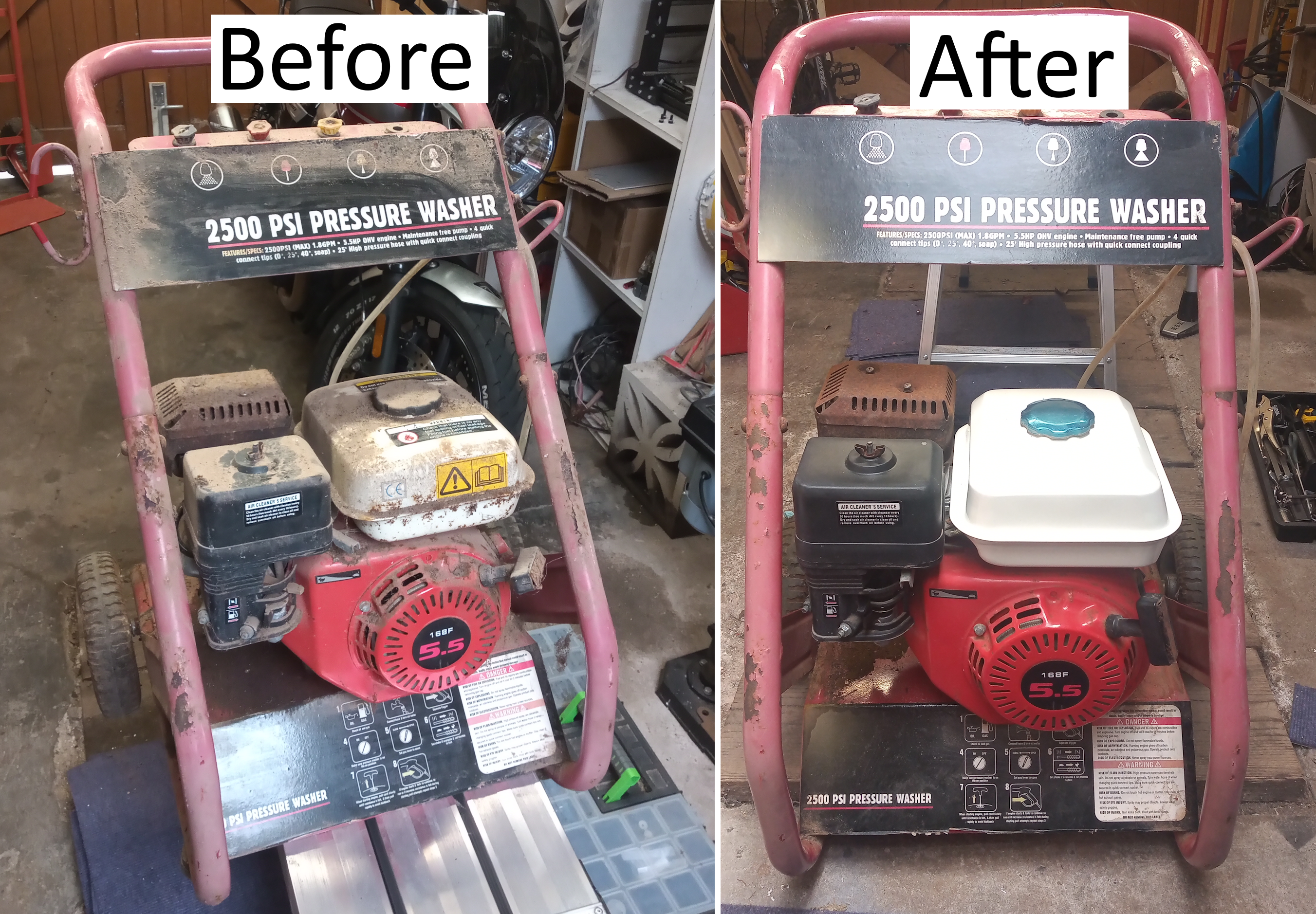
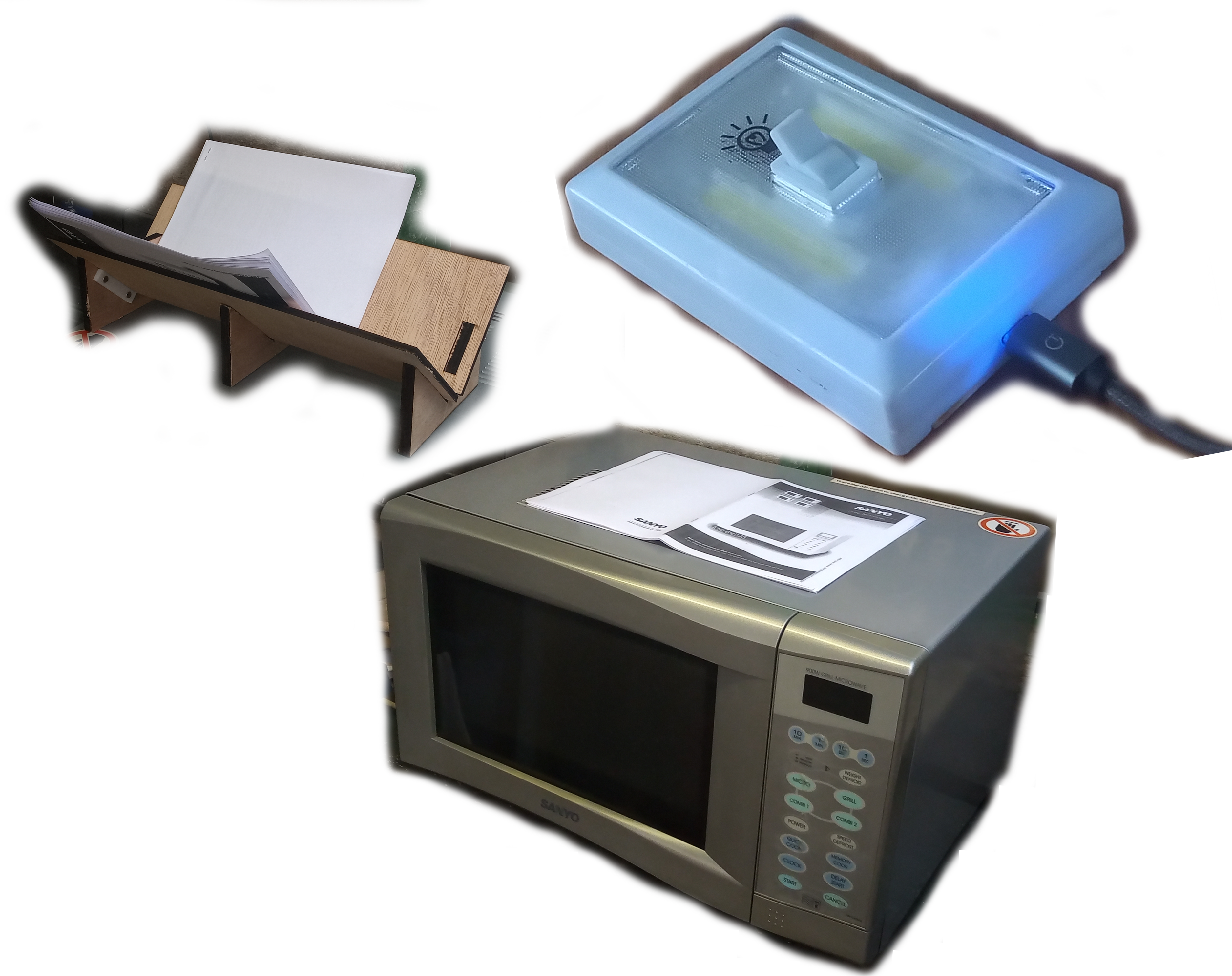
This pressure washer came to me from storage – I’m unsure on how long it had been in storage, nor if the storage was water-tight. […]
Copyright © 2025 | WordPress Theme by MH Themes