This a short how-to on interfacing with the Sharp infrared distance sensors, including wiring guides and tips for code and processing the signal.
This example is using the 10-80cm version (2Y0A21), however the principal is the same for the different versions. The 2-15cm version (0A51SK) was used with the Ender 3-D Scanner.
Pros & Cons
Pros:
- Inexpensive sensor (less than £5).
- There are different types with different distance ranges.
- The wiring is simple, only requiring 1 analog pin.
Cons:
- The output is very noisy.
- Every application will need reconfiguring for accurate results.
- The range is dependent on external factors and cannot detect clear objects.
Setup
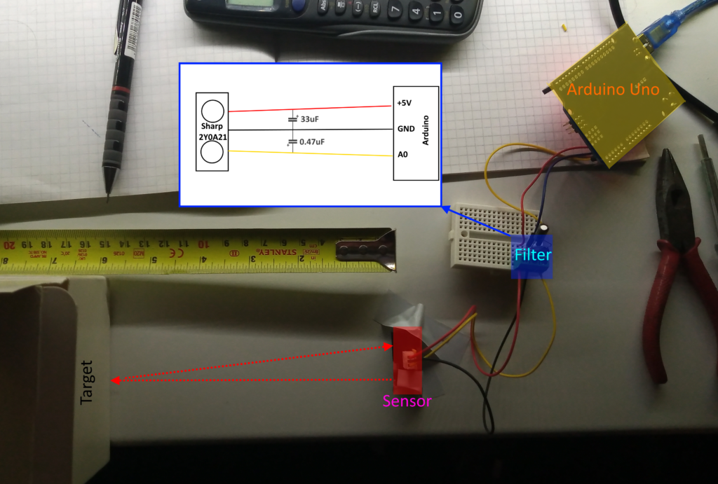
The sensor outputs a non-linear voltage dependant on the distance of the target from the sensor. This can be read using a single analog input pin, but the readings need to be calibrated to get a meaningful distance.
Ideally, the needs to be recalibrated for each application as changes on the 5V rail from other devices will change the voltage output.
The filter circuit was based on the works carried out by Aleksandar Haber – you can see is page here. I’ve also found that changing the 0.47uF electrolytic capacitor for a 0.01uF ceramic capacitor also returns good results. Changing the 33uF capacitor to a 330uF capacitor yields poorer results.
Regardless of the filter, output is still noisy – below is a screen shot from the serial plotter.
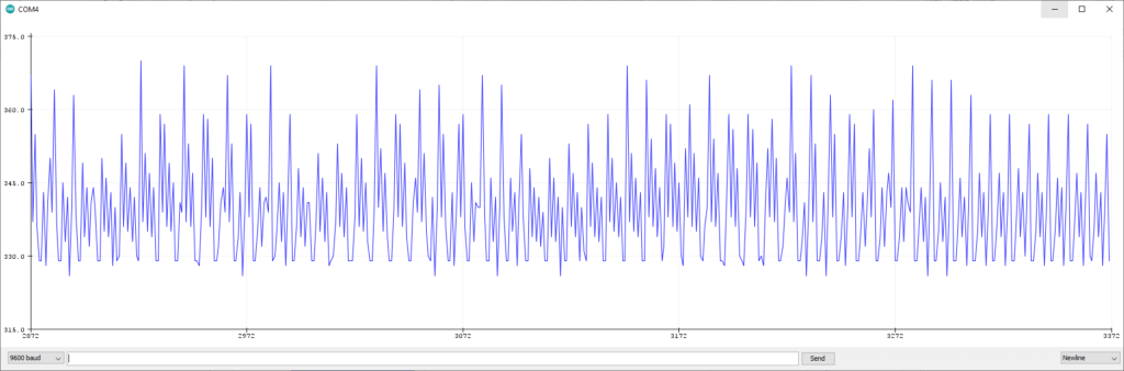
Being a lazy man, I’ve found a cheat to get a ‘real’ reading from this spikey mess. Essentially, find the modal average by taking two consecutive readings and compare them to each other. If they’re the same, then it’s a ‘stable’ reading.
This is the code:
void setup() {
  Serial.begin(9600);
}

void loop() {
  int reading1 = analogRead(A0);
  delay(35);
  int reading2 = analogRead(A0);
  if (reading1 == reading2) {
    Serial.println(reading1);
  }
  delay(50);
}
There is one major downside to this: speed (or lack of). The maximum rate for readouts I’ve achieved is 1.15Hz – this would be bollocks for any high-speed applications. (Infact, when using this type of sensor for the 3D scanner, a 0.04 mega-pixel scan would take several hours).
Put it all Together
With the above code running, set the target at pre-measured distances from the sensor and record the raw values in an excel document. From there, create an x-y scatter graph of the values against their intended measurements, insert a power-trendline and opt to view the equation.
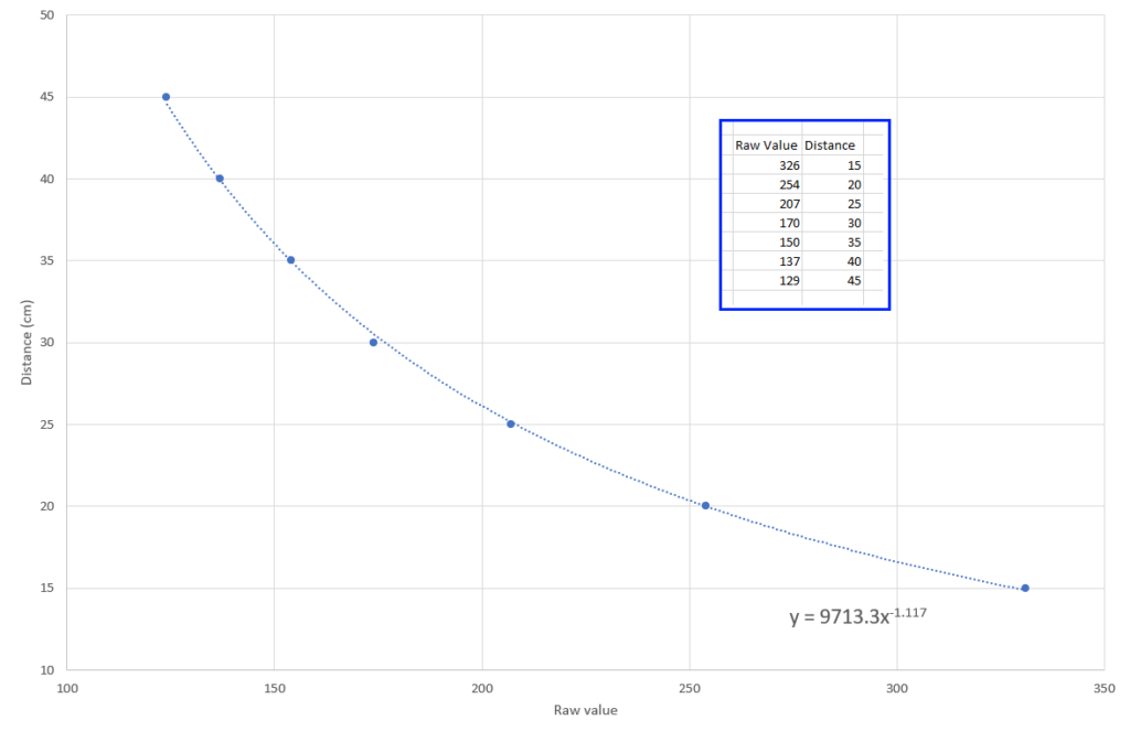
With the trendline equation you can then convert the raw value into a meaningful distance.
The code below takes the equation from above and uses it to calculate the distance and outputs the raw value and real distance to the serial monitor.
#include <math.h>

void setup() {
  Serial.begin(9600);
}

void loop() {
  int reading1 = analogRead(A0);
  delay(35);
  int reading2 = analogRead(A0);
  if (reading1 == reading2) {
    Serial.print(reading1);     //print raw value
    Serial.print(" , ");
    Serial.println(readingCMpow(reading1));   //print measurement in CM
  }
  delay(50);
}

double readingCMpow(int val) {
  return (9713.3 * pow(val, -1.117));  //insert figures from equation here
}
Conclusion
You get what you pay for with this sensor. There are many pitfalls, problems and hurdles to overcome, but, depending on your intended application, these could be overlooked.
There are other distance sensors that greatly outperform this IR sensor, such as the VL6180X laser ToF sensor. These are faster and much simpler to use, however, their beam divergence is approximately 15 degrees, whereas the IR sensor is closer to 5 degrees.
Last Updated: 22/11/2022