Important note: this setup uses the I2C bus for communication with the display. Therefore, the performance will be limited. If you want fast video in full colour then click here for the tutorial with a GC9A01 colour TFT display.
Hardware
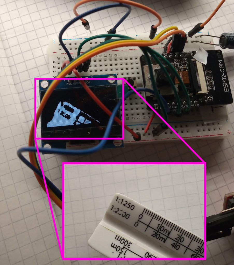
The photo shows the typical breadboard layout for the AI-thinker dev-board using an FTDI adapter to interface with the PC. The connections are better described here
This is the same SH1106 display written about here. However the connections this time are:
- Display Vcc = ESP32CAM 5V
- Display GND = ESP32CAM GND
- Display SDA = ESP32CAM GPIO 15
- Display SCL = ESP32CAM GPIO 13
The only positive factor of this project is that by utilising the I2C bus, there are spare GPIO pins available for other tasks.
Important note: GPIO 12 cannot be used as part of the I2C bus because the pull-up resistors bugger up the MCU’s ability to flash correctly.
Software
Important Note: there is no down-scaling used in this algorithm, so the display will show the upper-left 128×64 pixels from a 240×240 frame giving the output frame a crooked perspective with a narrow field of view. Oh, and it’s slow – taking about 640ms to complete a single frame.
#include "esp_camera.h"
#include <U8g2lib.h>
#include <Wire.h>

#define SDA_PIN 15
#define SCL_PIN 13

#define CAMERA_MODEL_AI_THINKER
#define PWDN_GPIO_NUM     32
#define RESET_GPIO_NUM    -1
#define XCLK_GPIO_NUM      0
#define SIOD_GPIO_NUM     26
#define SIOC_GPIO_NUM     27
#define Y9_GPIO_NUM       35
#define Y8_GPIO_NUM       34
#define Y7_GPIO_NUM       39
#define Y6_GPIO_NUM       36
#define Y5_GPIO_NUM       21
#define Y4_GPIO_NUM       19
#define Y3_GPIO_NUM       18
#define Y2_GPIO_NUM        5
#define VSYNC_GPIO_NUM    25
#define HREF_GPIO_NUM     23
#define PCLK_GPIO_NUM     22
The code starts with the normal camera declarations, along with including the necessary libraries.
camera_config_t config;

U8G2_SH1106_128X64_NONAME_F_SW_I2C u8g2(U8G2_R0, SCL_PIN, SDA_PIN);

uint8_t thresholdValue = 128; //set threshold range 0 - 255
Constructors and global variable.
void setup() {
  config.ledc_channel = LEDC_CHANNEL_0;
  config.ledc_timer = LEDC_TIMER_0;
  config.pin_d0 = Y2_GPIO_NUM;
  config.pin_d1 = Y3_GPIO_NUM;
  config.pin_d2 = Y4_GPIO_NUM;
  config.pin_d3 = Y5_GPIO_NUM;
  config.pin_d4 = Y6_GPIO_NUM;
  config.pin_d5 = Y7_GPIO_NUM;
  config.pin_d6 = Y8_GPIO_NUM;
  config.pin_d7 = Y9_GPIO_NUM;
  config.pin_xclk = XCLK_GPIO_NUM;
  config.pin_pclk = PCLK_GPIO_NUM;
  config.pin_vsync = VSYNC_GPIO_NUM;
  config.pin_href = HREF_GPIO_NUM;
  config.pin_sscb_sda = SIOD_GPIO_NUM;
  config.pin_sscb_scl = SIOC_GPIO_NUM;
  config.pin_pwdn = PWDN_GPIO_NUM;
  config.pin_reset = RESET_GPIO_NUM;
  config.xclk_freq_hz = 20000000;
  config.frame_size = FRAMESIZE_240X240;
  config.pixel_format = PIXFORMAT_GRAYSCALE;
  config.grab_mode = CAMERA_GRAB_LATEST;
  config.fb_location = CAMERA_FB_IN_PSRAM;
  config.jpeg_quality = 12;
  config.fb_count = 2;

  esp_err_t err = esp_camera_init(&config);

  sensor_t * s = esp_camera_sensor_get();
  s->set_brightness(s, 0);     // -2 to 2
  s->set_contrast(s, 0);       // -2 to 2
  s->set_saturation(s, 0);     // -2 to 2
  s->set_special_effect(s, 0); // 0 to 6 (0 - No Effect, 1 - Negative, 2 - Grayscale, 3 - Red Tint, 4 - Green Tint, 5 - Blue Tint, 6 - Sepia)
  s->set_whitebal(s, 1);       // 0 = disable , 1 = enable
  s->set_awb_gain(s, 1);       // 0 = disable , 1 = enable
  s->set_wb_mode(s, 0);        // 0 to 4 - if awb_gain enabled (0 - Auto, 1 - Sunny, 2 - Cloudy, 3 - Office, 4 - Home)
  s->set_exposure_ctrl(s, 1);  // 0 = disable , 1 = enable
  s->set_aec2(s, 0);           // 0 = disable , 1 = enable
  s->set_ae_level(s, 0);       // -2 to 2
  s->set_aec_value(s, 300);    // 0 to 1200
  s->set_gain_ctrl(s, 1);      // 0 = disable , 1 = enable
  s->set_agc_gain(s, 0);       // 0 to 30
  s->set_gainceiling(s, (gainceiling_t)0);  // 0 to 6
  s->set_bpc(s, 0);            // 0 = disable , 1 = enable
  s->set_wpc(s, 1);            // 0 = disable , 1 = enable
  s->set_raw_gma(s, 1);        // 0 = disable , 1 = enable
  s->set_lenc(s, 1);           // 0 = disable , 1 = enable
  s->set_hmirror(s, 0);        // 0 = disable , 1 = enable
  s->set_vflip(s, 0);          // 0 = disable , 1 = enable
  s->set_dcw(s, 1);            // 0 = disable , 1 = enable
  s->set_colorbar(s, 0);       // 0 = disable , 1 = enable

  u8g2.begin();
  u8g2.setDrawColor(1);
  Serial.begin(115200);

}
Setup function. Note that the PIXFORMAT is set to GRAYSCALE to give a 0-255 value.
void loop() {
  long startTime = millis();
  u8g2.clearBuffer();
  camera_fb_t  * fb = NULL;
  fb = esp_camera_fb_get();

  for (int i = 0; i < 8192; i++) {
    int line = floor(i / 128);
    int row = i % 128;
    int framePixel = fb->buf[(line * 240) + row];
    if (framePixel > thresholdValue) {
      u8g2.drawPixel(row, line);
    }
  }

  u8g2.sendBuffer();
  esp_camera_fb_return(fb);   //return the frame buffer back to the driver for reuse
  long frameTime = millis() - startTime;
  Serial.println(frameTime);
}
The loop function is simple.
The camera takes a picture, then the value of the top left 128×64 pixels are checked against a threshold value and will draw a pixel at that point if the threshold is met.
Repeat a further 8191 more times, and then send the buffer to the display.
Simple.
Conclusion
Below is evidence that the setup does work, albeit poorly. I’m not au-fait with the u8g2 library; so there could be great optimisation available.
However, this project was driven more by curiosity, and the piss-poor refresh rate means it’s a non-starter for any future camera projects.
1-bit selfie:
The video shows the abysmal refresh rate:
If I had more time then I would like to implement some sort of dithering algorithm (just to learn about them), as well as better camera pixel sub-sampling to widen the field of view.
I did fuck about with a 1024 byte array and then converting 8 pixel chunks into a single byte. But my programming is janky and the ESP32 just shit a brick.
Page created: 05/03/2025
Last updated: 05/03/2025