Hints and tips on how to use the SR505 PIR sensor with an Arduino Nano & ESP32-CAM. Yes, the goal is to create a motion detection camera.
Hardware
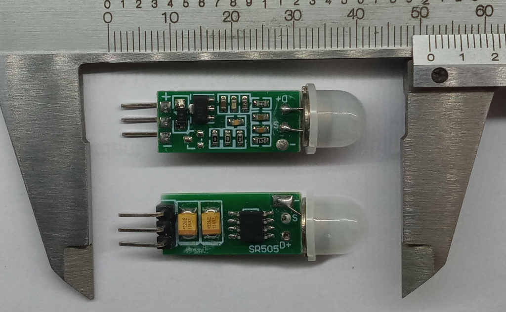
The pin out is simple:
- Connect 5V to the pin marked with a ‘+’ symbol. This has to be 5V. It will not work with 3.3V.
- Connect the pin marked with a ‘-‘ symbol to ground. No brainer.
- The middle pin is data out. This will output a digital high upon detecting new motion. The pin will go low only after 8 seconds of no movement; any new movement resets the timer.
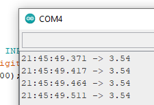
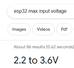
Using the ADC on the Arduino Nano, the voltage of this pin was measured at 3.5V. This is within the 3.6V tolerance of the ESP32.
Software
Arduino
The best way to use this module is with interrupts. Connect the data pin of the module to D2 on the Arduino Nano (or Uno) and the following code will give a simple test.
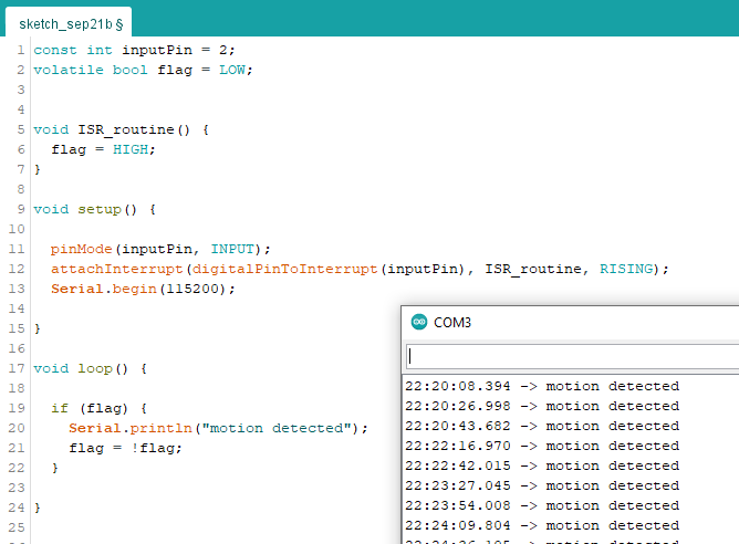
ESP32-CAM
The setup for the ESP32-CAM is almost identical except that the output pin from the sensor should be connected to GPIO 13. The code will need to be altered to suit
Substitute line 1 with this:
const int inputPin = 13;substitute line 5 with this:
void IRAM_ATTR ISR_routine() {Future Plans
The immediate plan is to use the rising edge from the sensor to trigger the camera on the ESP32-CAM. I will be using the example written by Rui & Sara Santos at Random Nerd Tutorials to hopefully guide me.
The working camera will be put to use to monitor the cat litter box and left until the batteries die.
This test serves two main purposes. Firstly, the test will give real world battery performance. Secondly, the photos captured during the test can be used for machine learning to determine if it’s the cat going for a shit or the dog eating the cat litter….
Last Updated: 21/09/2023