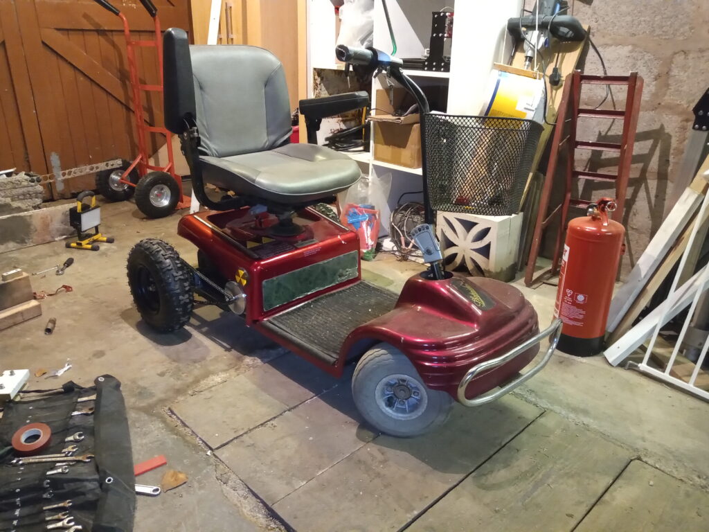
After the successful conversion of a bicycle to a 1000W eBike; this was the obvious progression: swap the standard motor out of a mobility scooter for something stupidly large and add a few more batteries; how hard can that be?

Apparently the answer is, “very”.
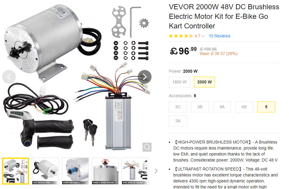
The existing motor was part of a whole motor-axle-brake-wheel assembly that was bolted to a simple chassis. The dream that this was going to be a simple motor swap was gone and a new rear axle assembly was ordered along with the 2000W motor.

For ease of testing, a 48V system was selected for compatibility with the existing eBike.
The controller is rated for 33 Amps; so for 48V = 1584 W. Opting for a 14s li-ion battery would still only yield 1940 W.
Regardless, this is greater than the original 750W / 24V system.
The motor is rated to 4300 RPM giving 815 RPM at the axle with a gearing of 11T at the motor and 58T on the axle. With 12.9 inch tyres the max theoretical speed is 31mph. Terrifying.
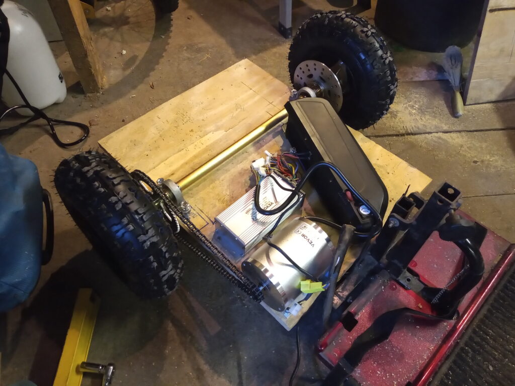
The first test chassis consisted of 18mm thick ply bolted to the original frame with threaded bar and nuts.
The battery was from the eBike and the power connection was made by jamming an M4 screw into the terminals. (Not recommended – produces a spark).
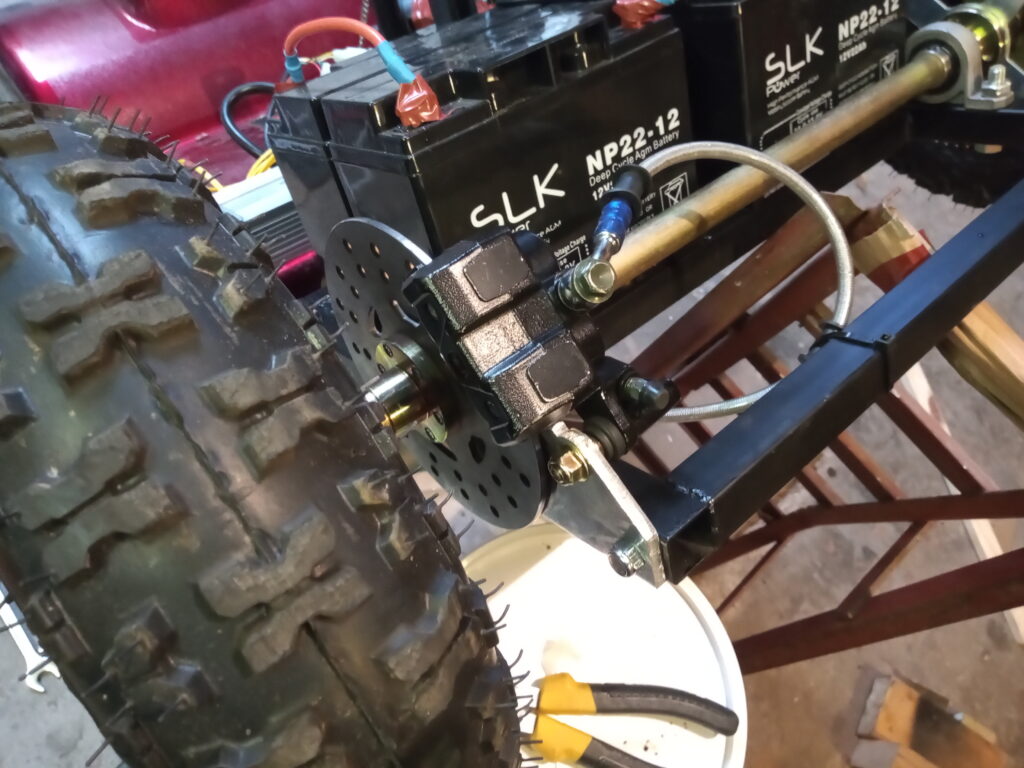
To power the craft, lead-acid chemistry was chosen with four 22Ah batteries in series to give 48V 22Ah. The other advantages are it’s relative simplicity and cost. A li-ion battery of the same capacity would be over double the price and not have the same discharge rates. However, slenderness is sacrificed – the total mass of the 4 units is about 25kg.
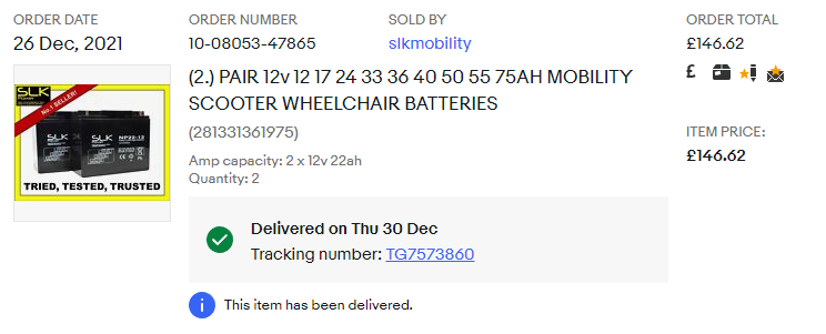
In regards to range, if the controller was at full power (33 Amp) then the batteries would discharge within 40 mins. Assuming a nominal speed of 20mph gives a ball-park figure of 13 miles. Modest, but enough to launch you to the shops and back.
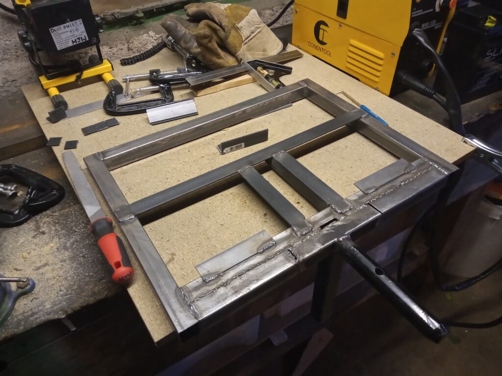
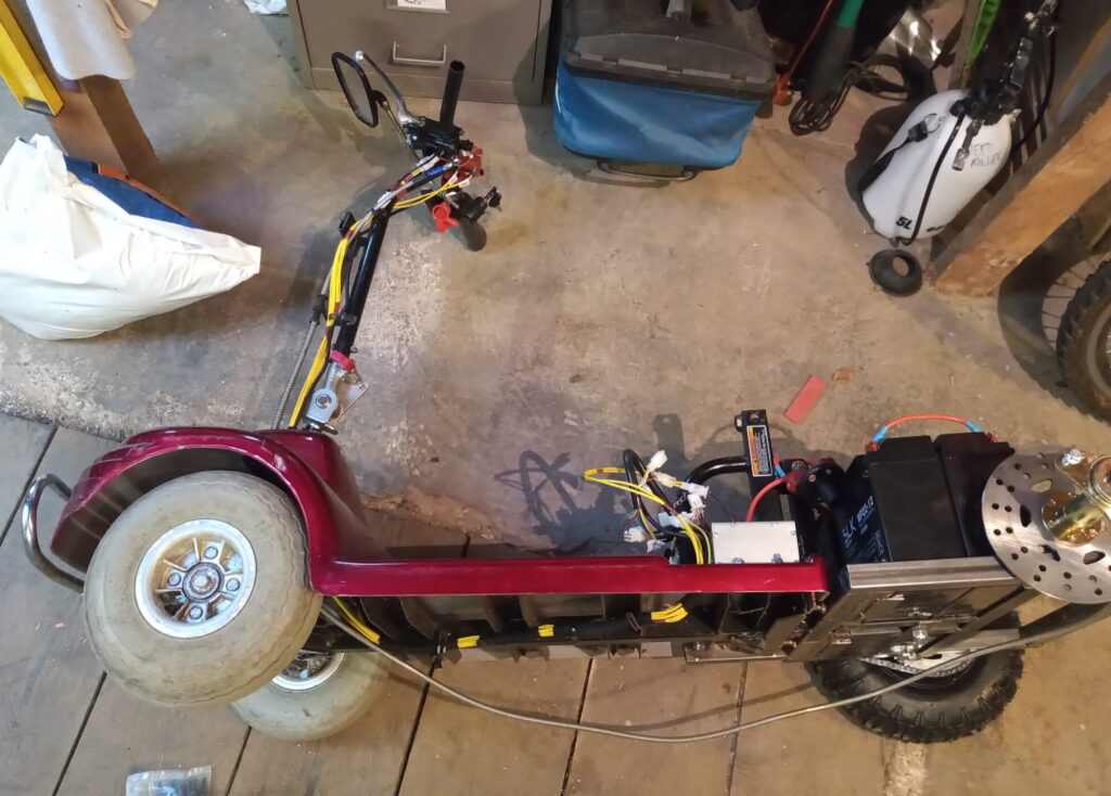
The existing rear chassis was cut back and a new chassis was formed with some square hollow section. Mild steel angle and flat bar was used to form the battery holder
The metal was fixed together using a MIG welder (my first welding project).
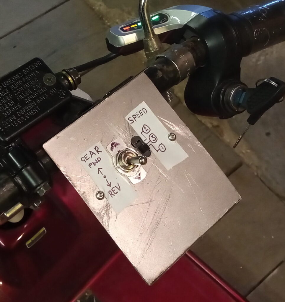
Controls for the scooter are simple; there is a toggle switch for forward and reverse. If the switch is made then the reverse ‘gear’ is ‘engaged’.
There are three speeds to choose from (1 – 3) with 1 being the slowest and 3 the fastest.
The large expanse of empty metal at the bottom of the control board is to house a future 16×2 LCD screen. The screen will display the speed of the vehicle. (Send your Vmax guess via the Contact page)
All the cabling is done in 18AWG wire using crimped connectors at each end (with exception of the spade connectors for the direction switch).
The loom also incorporates the brake lever kill switch and throttle cables.
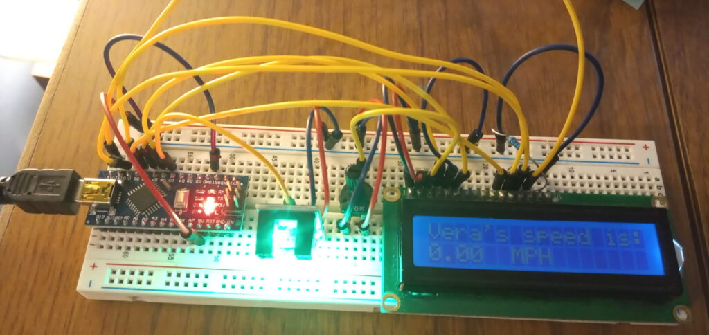
An Arduino Nano, IR light gate and 16×2 LCD screen form the basis of the speedometer using the same underlying code as the Wank-o-meter, as seen below.
It’s important that the ‘startTime’ and ‘endTime’ variables are declared as a ‘long’ type. If you use an ‘int’ then the program hangs after about 32 seconds. Ask me how I know.
int takeMeasure() {

  int stepCount = 0;

  long startTime = millis();
  long endTime = startTime + 1000;     //1.0s sample rate

  while (millis() < endTime) {
     if (digitalRead(sensor)) {
        stepCount = stepCount + 1;
        while (digitalRead(sensor));
     }
  }

  return stepCount;

}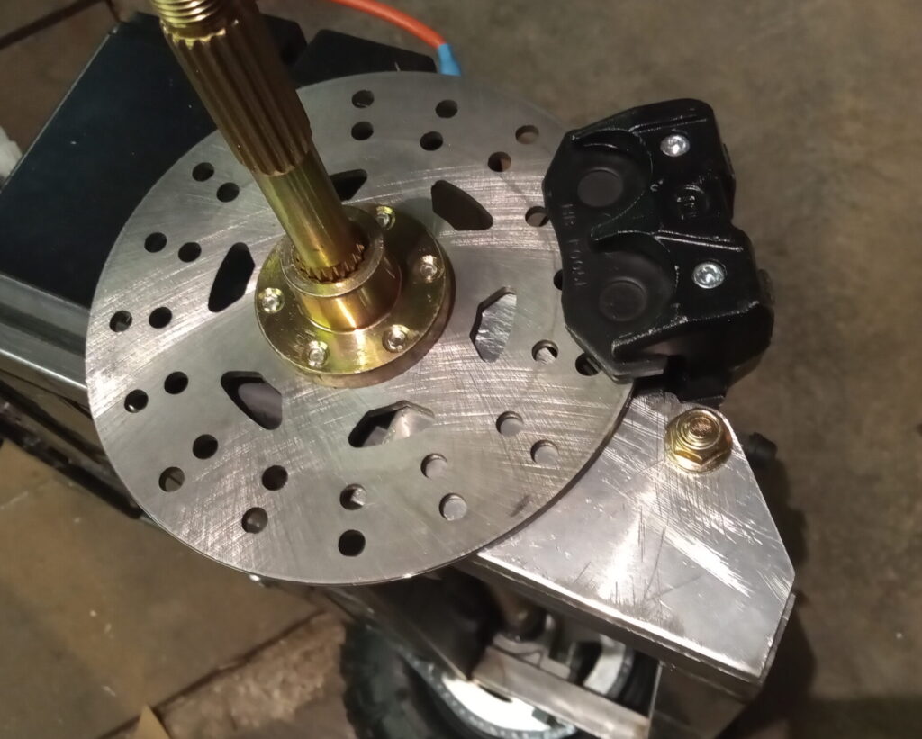
Progress has also been made in the brake system; a custom bracket has been fabricated from 6mm aluminium plate.
A template was made using cardboard and transferred and the majority of the fabrication was done using a jigsaw and hand files.
Next jobs on the list of things to sort are:
- Mount the speedo sensor, screen and Arduino.
- Solve the Arduino power problem (stepping down from 48v battery to 5v – waiting on parts).
- Lights would be cool, but not essential.
Change of Plan
New front tyres were fitted to overcome the horrendous oversteer, but the live axle design for the rear was never the best. The brakes were also poor at best and would barely hold you on a slope.
A top speed of 18mph was recorded on a test run with minimal handling and piss-poor brakes, that is terrifying.
In short: this was a bad idea from the start – so therefore the motor is being donated to the Electric Quad Bike.
Not going to rule out the possibility of making this a petrol powered mobility scooter… But one thing at a time.