This project was inspired by a post on Reddit.
It is a single frame scanner that outputs an 80×80 pixel image to a colour TFT display to combine LiDAR scanning with colour imagery, to effectively create night-vision.
Along the way, some funky colouring was achieved; hence LiDARt!
Hardware
Thankfully the majority of this project had already been constructed as part of the current LiDAR project.
A pair of NEMA17 stepper motors and A4988 drivers control the azimuth and elevational rotation while the distance is measured with the Benewake TF Luna LiDAR sensor.
The only hardware changes that were required was the omission of the user input control and changing the screen from the original 128×64 monochrome OLED to a 240×240 colour TFT display.
Operation & Movement
In recent tests, I had found that not all microsteps are equal. Microstepping the motor greater than half step results in poor accuracy. Therefore at half step the NEMA17 motor will be doing 400 steps per revolution.
If each pixel in the display was attributed to a step of the motor then the field of view would be 216 degrees and the resulting image would have had severe fish-eye distortion.
As such, the resolution of the TFT display was divided in to 3×3 pixel squares to reduce the overall image size to 80×80 pixels and the field of view to 72 degrees.
The scanner would operate by taking a measurement, converting the distance to a colour, drawing the colour to the display, advancing the azimuth stepper motor and repeating another 79 times.
At the end of the row, the elevation stepper motor would move down and the azimuth stepper would return to the start of the new row.
A single image would take just over 3 mins to be created, thus yielding approximately a scan rate of 35.5 pixels per second.
The refresh rate on the sensor is limited to 100Hz and is slowed down by the movement of the stepper motors.
Colours & Conundrums
While the X & Y co-ordinates were simple to display, the depth required a conversion of a distance to a nominal colour. This turned out to be difficult.
The display uses a 16bit RGB565 format where the first 5 bits represent the level of blue, the next 6 bits represent the level of green and the final 5 bits represent the level of red. This gives a total of 65,535 colours.
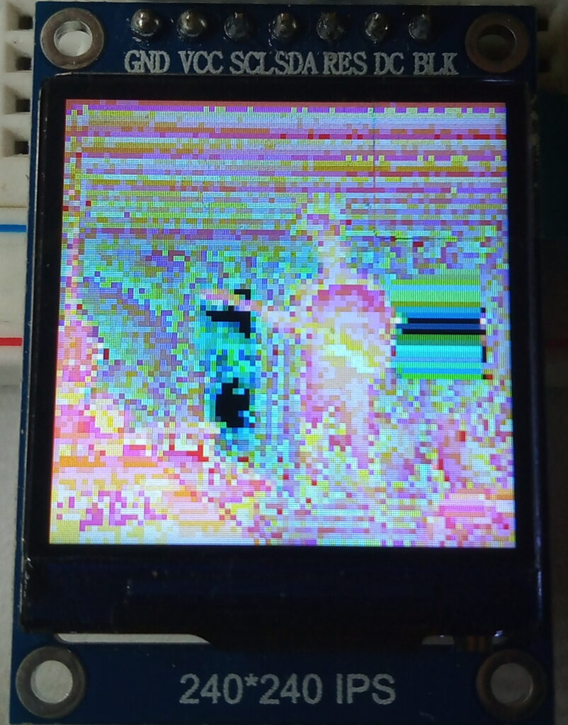
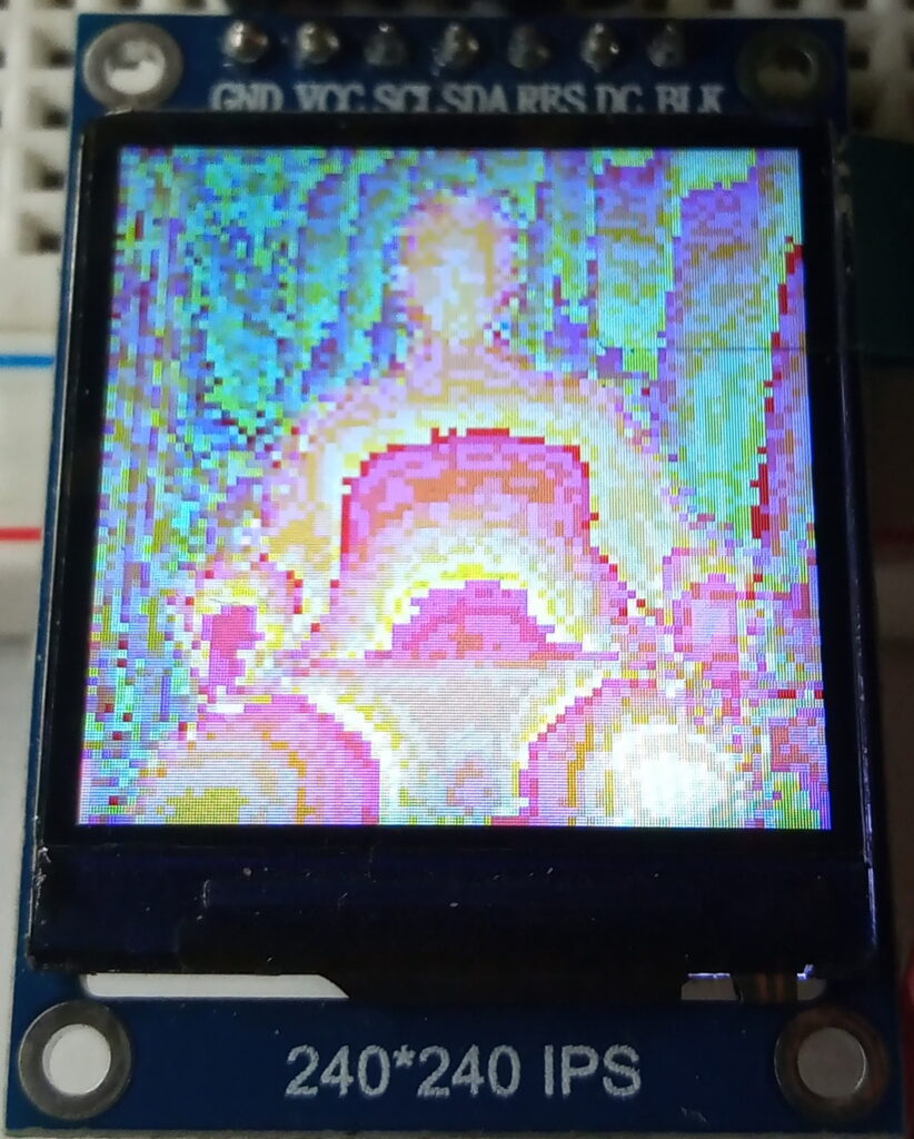
The first attempt at colouring the image involved inversely mapping the distance against a number between 0-65,535. While this method is wonderfully simple, it’s also is massively flawed.
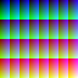
This is because colour number zero is black, colour number 1 is dark blue, colour number 2 is a slightly lighter dark blue and so on until you reach colour number 32 which reverts back to black + 1/64th green, as demonstrated in the table below.
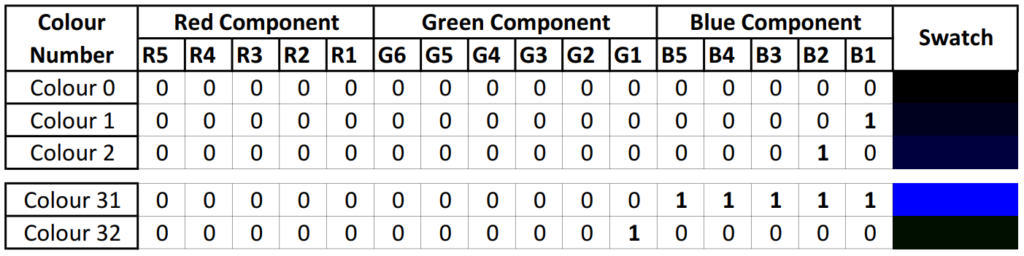
In short, after the first 5 bits fill up, the counter rolls over and adds one to the least significant bit of the green component. As a result of this, the full 16 bit colour scans produce strange and fascinating colours.
There is a well written page by Barth Development on the nuances of the RGB888 and RGB565 colour palettes.
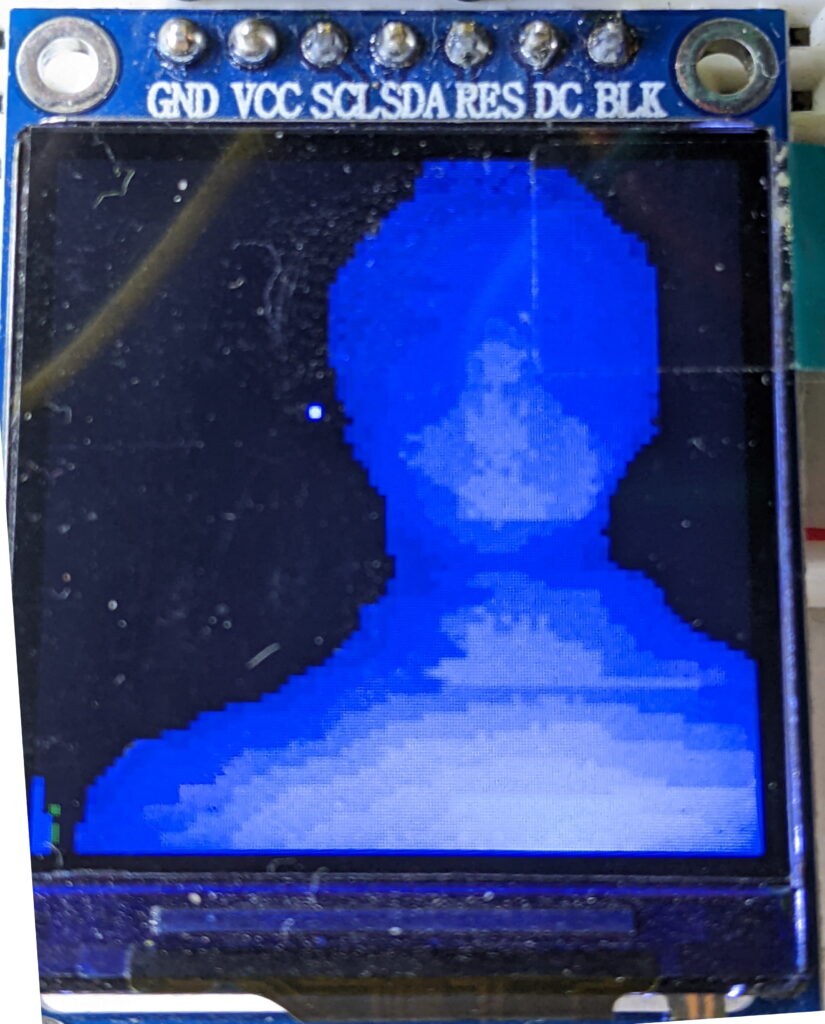
In a vain attempt to get the depth to be correctly represented by a colour, the code was adapted to map a smaller distance range to the first 32 colours. So there are a selection of 5 bit blue versions, too.
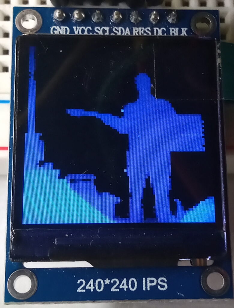
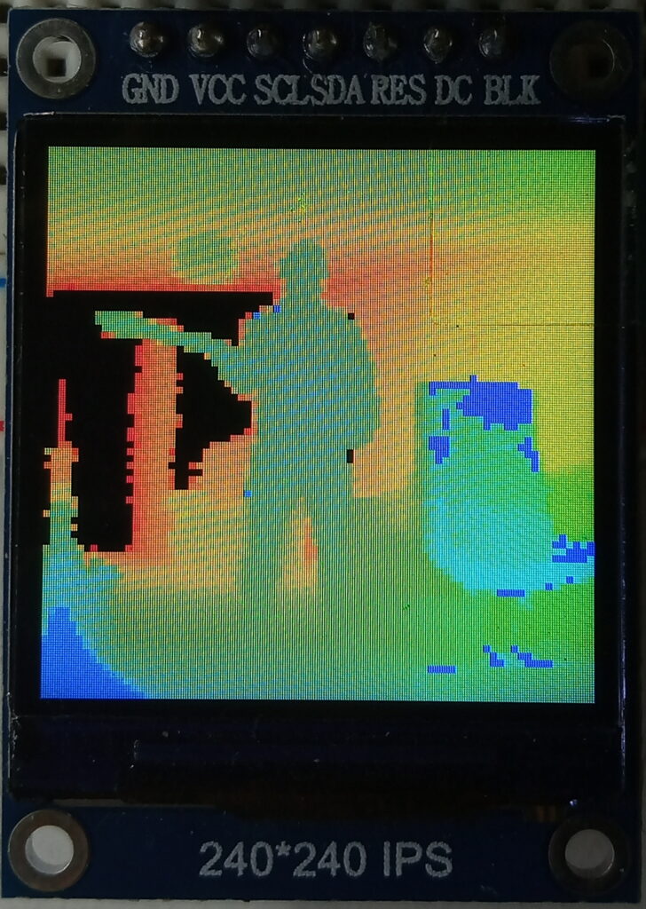
After sleeping on the problem, the solution was realised by splitting the distances in to bands, mapping the bands to their respective RGB components and bit shifting them to suit the 16 bit RGB565 display.
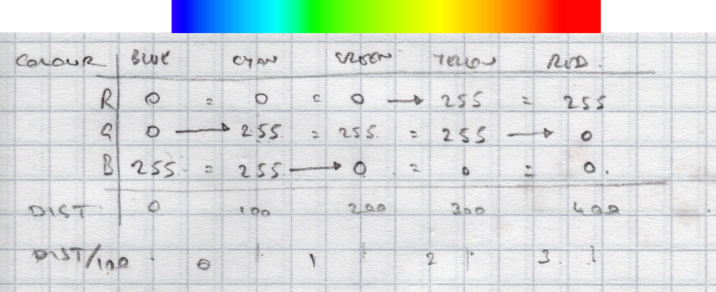
Doing this gives 128 different colours. Fading the blue to black at the start of the run and the red to black at the end gives a total of 192 colours.
Code
Here is the code; it will probably be highly inefficient. However, as someone once said: if it looks stupid but it works, then it’s not stupid.
If it doesn’t compile for you then it could be because I’ve edited it to look nicer on here. Feel free to contact me if you have issues.
Includes, Object Creation & Global Variables
The pinout is based on an ESP32 Dev kit. Obviously, feel free to change these to suit your MCU and development board.
Note that the variables to do with colour are unsigned integers to handle the large numbers.
#include <Wire.h>
#include <TFLI2C.h>
#include <TFT_eSPI.h>
#include <SPI.h>

TFT_eSPI tft = TFT_eSPI();

TFLI2C tflI2C;

int16_t tfAddr = TFL_DEF_ADR;
int16_t tfDist;

const int rotMotorStep = 25;
const int rotMotorDir = 26;
const int elvMotorStep = 16;
const int elvMotorDir = 17;
const int rotMicroStep = 33;
const int elvMicroStep = 32;

int pixelX = 0;
int pixelY = 0;
unsigned int pixelColour;
unsigned int distanceColour;

unsigned int R = 0;
unsigned int G = 0;
unsigned int B = 0;
Setup & initialisations
It’s noted in the code, however, the microstep pins of the MCU are wired to all microstep pins of the driver (MS1, MS2 & MS3). Driving this pin HIGH gives 1/16th microstep, driving it LOW gives full step.
void setup() {


  Wire.begin();

  tft.init();
  tft.fillScreen(TFT_BLACK);  //clear screen
  tft.setSwapBytes(true);

  pinMode(rotMotorDir, OUTPUT);
  pinMode(rotMotorStep, OUTPUT);
  pinMode(elvMotorDir, OUTPUT);
  pinMode(elvMotorStep, OUTPUT);
  pinMode(rotMicroStep, OUTPUT);
  pinMode(elvMicroStep, OUTPUT);

  digitalWrite(rotMicroStep, HIGH); //hardwired to 1/16th microstep
  digitalWrite(elvMicroStep, HIGH); //hardwired to 1/16th microstep

  delay(5000);

}
Main Loop
Technically, this is an oxymoron, as the ‘loop’ is a single shot and then hangs on the while(1) command until the user presses the reset button.
void loop() {
  //scan 80x80 grid, outputting 3x3px = 240x240 display
  //microstep enabled to 1/16th for smoothness
  //half step (8 microsteps) = 400 step per rev.
  //total 80 steps = 72degree FOV

  //set row
  for (int e = 0; e < 80; e++) {
    pixelY = e * 3;
    //scan row
    for (int r = 0; r < 80; r++) {
      pixelColour = getColour();
      pixelX = r * 3;
      tft.fillRect(pixelX, pixelY, 3, 3, pixelColour);
      stepCCW(8);
      delay(10);  //100hz refresh on scanner
    }
    stepCW(640);
    stepDown(8);
  }
  stepUp(640);
  while (1);
}
Theoretically, you could let the loop repeat and it would operate as a continuous scanning camera, albeit with a very low frame rate (approx 0.005 FPS). I’ve not tested this, yet.
Colour mapping function
This function is where the magic happens.
The distance is run through a series of IF statements to decide where it lies in the spectrum and then has the relevant colour mapped.
These components are then bit shifted to suit the RGB565 format. The red component is moved 11 places and the green is moved 5 places.
uint16_t getColour() {
  //192 colour, 0-384cm range, 2cm resolution
  if (tflI2C.getData(tfDist, tfAddr)) {
    if (tfDist > 0) {
      //black - blue
      R = 0;
      B = map(tfDist, 0, 63, 0, 31);
      G = 0;
    }
    if (tfDist > 63) {
      //blue - cyan
      R = 0;
      B = 31;
      G = map(tfDist, 10, 73, 0, 31);
    }
    if (tfDist > 127) {
      //cyan - green
      R = 0;
      B = map(tfDist, 127, 191, 31, 0);
      G = 31;
    }
    if (tfDist > 191) {
      //green - yellow
      R = map(tfDist, 191, 255, 0, 31);

      B = 0;
      G = 31;
    }
    if (tfDist > 255) {
      //yellow - red
      R = 31;
      B = 0;
      G = map(tfDist, 255, 319, 31, 0);
    }
    if (tfDist > 319) {
      //red - black
      R = map(tfDist, 319, 383, 31, 0);
      B = 0;
      G = 0;
    }
    if (tfDist > 383) {
      //black
      R = 0;
      B = 0;
      G = 0;
    }
    distanceColour = ((R << 11) + (G << 6) + (B));
  }
  return distanceColour;
  }
}
In the interests of openness; here are the two previous sections of code for the 5 bit blue and 16 bit colour options.
16 Bit Colour
//16bit (65535) colour over 0-600cm distance range
    if (tflI2C.getData(tfDist, tfAddr)) {
      if (tfDist < 600) {
        distanceColour = map(tfDist, 0, 600, 65535, 0);
      } else {
        distanceColour = 0;
      }
    }
5 Bit Blue
//32colour bluescale over distance of 0-64cm
    if ( tflI2C.getData( tfDist, tfAddr)) {
      if (tfDist < 65) {
        distanceColour = map(tfDist, 0, 64, 32, 0);
      } else {
        distanceColour = 0;
      }
    }
Stepper control
The number passed to these functions is the number of 1/16th microsteps to take. Therefore, to do a complete 360 degree rotation you’ll need to pass (3200) to the function.
Having 1/16th microstep allows for greater smoothness of the motor motion and also the ability to change the stepping with software.
void stepCW(int steps_) {
  for (int i_ = 0; i_ < steps_; i_ ++) {
    digitalWrite(rotMotorDir, LOW);
    digitalWrite(rotMotorStep, HIGH);
    delayMicroseconds(500);
    digitalWrite(rotMotorStep, LOW);
    delayMicroseconds(500);
  }
}
/////////////////////////////////////////////
void stepCCW(int steps_) {
  for (int i_ = 0; i_ < steps_; i_ ++) {
    digitalWrite(rotMotorDir, HIGH);
    digitalWrite(rotMotorStep, HIGH);
    delayMicroseconds(500);
    digitalWrite(rotMotorStep, LOW);
    delayMicroseconds(500);
  }
}
/////////////////////////////////////////////
void stepUp(int steps_) {
  for (int i_ = 0; i_ < steps_; i_ ++) {
    digitalWrite(elvMotorDir, HIGH);
    digitalWrite(elvMotorStep, HIGH);
    delayMicroseconds(500);
    digitalWrite(elvMotorStep, LOW);
    delayMicroseconds(500);
  }
}
/////////////////////////////////////////////
void stepDown(int steps_) {
  for (int i_ = 0; i_ < steps_; i_ ++) {
    digitalWrite(elvMotorDir, LOW);
    digitalWrite(elvMotorStep, HIGH);
    delayMicroseconds(500);
    digitalWrite(elvMotorStep, LOW);
    delayMicroseconds(500);
  }
}
Results
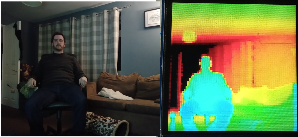
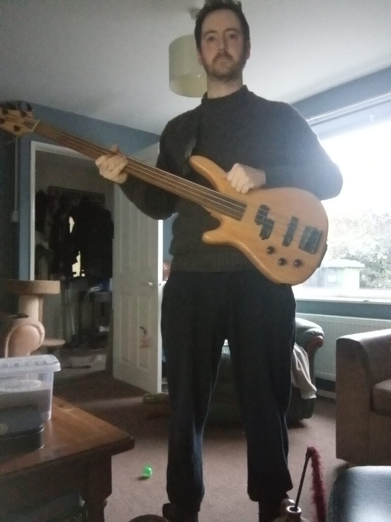
Here are some photos of the results achieved and the test subjects.
Photo
16 Bit Colour
5 Bit Blue
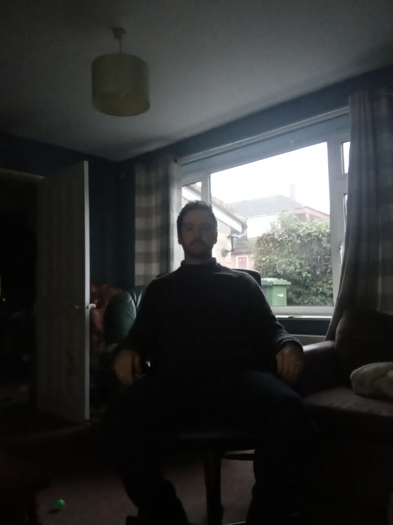
Photo
16 Bit Colour
5 Bit Blue
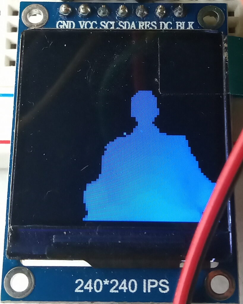
5 Bit blue portrait
128 colour pose
Conclusion and Future Plans
This was a nice weekend project to distract me from the maths problems of the LIDAR project and the mechanical design of the Bark Blind.
The XY resolution could be increased by reducing the pixel size and using 1/4 or 1/8th steps. However, the FoV of the sensor is 2 degrees, so there would be minimal gains.
Overall, I’m genuinely happy how this project has turned out. I’m particularly chuffed that I’ve managed to get the colour gradient working, especially as it’s my first project to use bit shifting.
Last updated: 08/01/2023