
This module is a cheap and effective sound sensor that has been used extensively within the Bark Blind project. This write up includes all of the wiring diagrams and code needed to test, verify and calibrate your KY-037 sound sensor using an Arduino Nano.
These tests focus on measuring the amplitude of the output, so if you’re looking for anything to do with pitch analysis or voice detection then search elsewhere.
Hardware
They say a picture paints a thousand words, so below is a photo of the physical setup used used to test these modules. The pinout is:
- KY-037 AO –> Arduino A0
- KY-037 G –> Arduino Ground
- KY-037 + –> Arduino 5V
- KY-037 DO –> Arduino D2
The image at the top of this page can be used as a reference.

Software
//KY-037 Mic module

const int sensor_digital = 2;   //connected to DO on module
const int sensor_analog = A0;   //connected to AO on module

void setup() {

  pinMode(sensor_digital, INPUT);
  pinMode(sensor_analog, INPUT);
  Serial.begin(115200);

}

void loop() {

  int analog_value = analogRead(sensor_analog);
  int digital_value = digitalRead(sensor_digital);

  Serial.print("Analogue value = ");
  Serial.println(analog_value);

  if (digital_value == 0) {   //digital output is inverted
    Serial.println("Digital pin triggered");
  }

  delay(20);  //50Hz sample rate

}
This is a simple sketch reads the analogue values of the sound sensor module, and outputs the analogue value to the serial monitor.
The digital output is also monitored and will post a message to the serial monitor if it is triggered.
Testing & Calibration
Calibrating
The value of the analogue output can be calibrated by rotating the brass screw on the trimpot: turning screw clockwise will decrease the value, and turning the screw anti-clockwise will increase the analogue value.
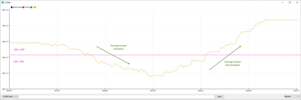
Note that the digital output LED is inverted, so when the analogue value drops below 512 the LED turns on, and conversely, when the analogue output is above 512, the digital output LED turns off.
Testing
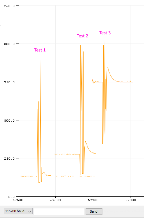
Without a way of creating a controlled sound to test, it’s not possible to give any solid advice. This graph shows what happens when you blow on the microphone at different analogue values.
There does seems to be a pattern in that the higher the analogue value, the lower the range of values and longer the duration – however, this wasn’t a controlled or repeated test, so could be a complete fluke.
Regardless of that, it shows what happens to the output and gives an indication of the type of interrupt trigger required; for example Test 1 would respond to a RISING trigger when a strong peak (greater than 512) is detected, whereas Test 3 would respond to a FALLING trigger (lower than 512). In all instances, a CHANGE trigger would respond to a strong signal.
Digging Deeper
Deep Sleep & Interrupts
Altering the code used within the “Wake an Arduino IR Receiver” page, it’s easy to set up the microphone and as the “alarm” to wake the Arduino as a lower powered listening device.
As previous this uses the LowPower.h library, and an interrupt.
Note this setup requires the digital output of the microphone connected to either pins D2 or D3 for a standard Arduino Uno/Nano (Any interrupt enabled pin).
If you’re using motors (or other large loads) in your circuit, then the voltage drop can cause a false trigger.
#include "LowPower.h"

const int mic_digital_pin = 2;

/////////////////////////////
void ISR_flag() {

}
//////////////////////////////////////////////
void setup() {
  Serial.begin(115200);

  attachInterrupt(digitalPinToInterrupt(mic_digital_pin), ISR_flag, CHANGE);
}
//////////////////////////////////////////////
void loop() {
  Serial.println("Time for sleep...");
  delay(200);
  LowPower.powerDown(SLEEP_FOREVER, ADC_OFF, BOD_OFF);
  Serial.println("...I'm awake now");
  delay(1000);
}
Barebones Hardware
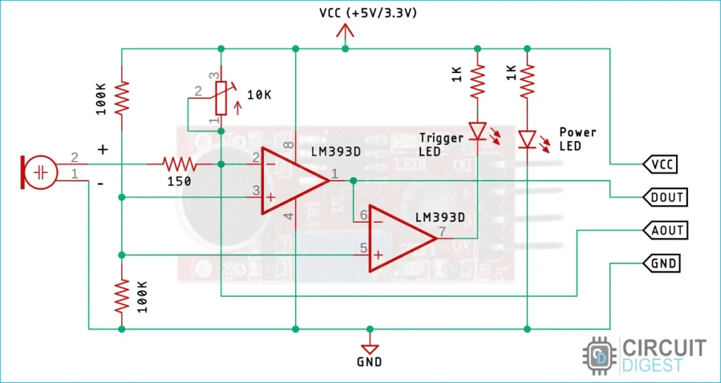
The schematic for this sound sensor is shown below (courtesy of Circuit Digest, who go in to more detail with these modules and ESP32s) The schematic shows that the module uses one half of an LM393 comparator to drive the digital output pin, with the inverting input connected to the bias trim-pot.
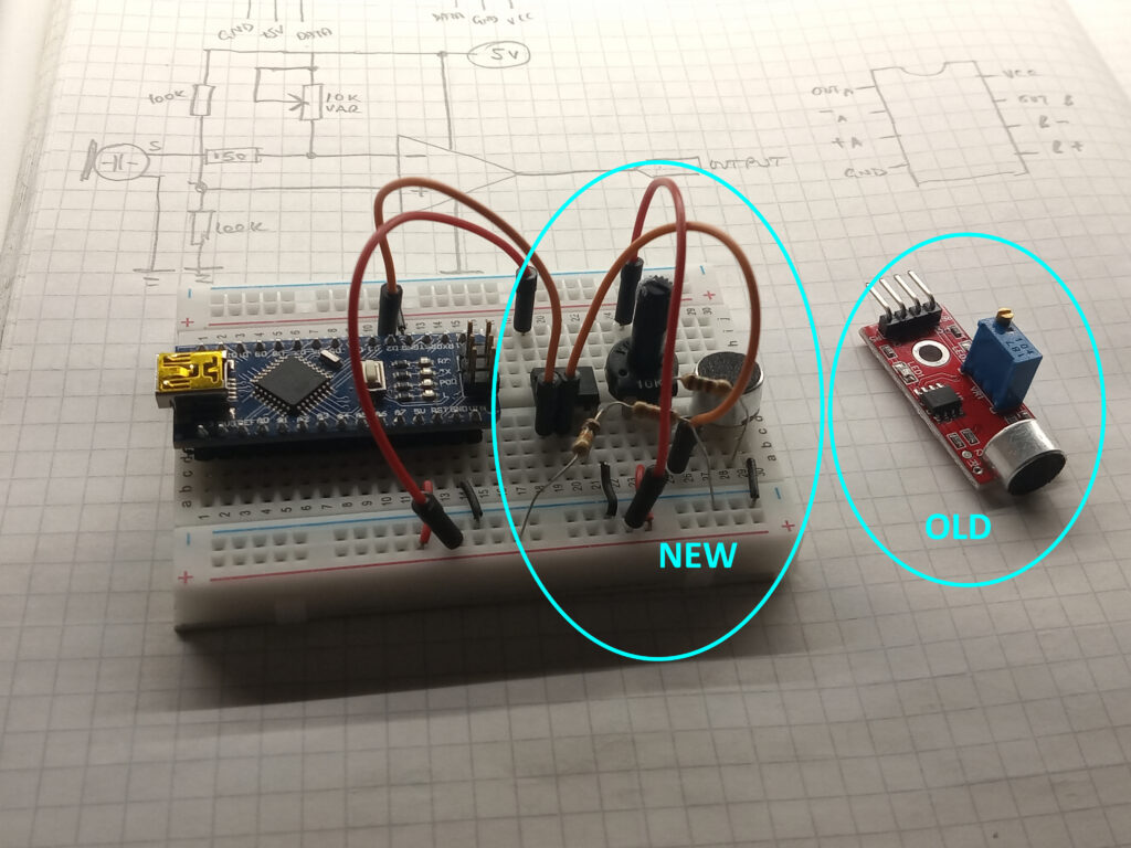
To reduce current consumption from the LEDs, it is possible to build your own “module” using discrete components – this can also be helpful for reducing board space and simplifying the circuit. In this instance, an LM358 Op-amp was used as a result of “the best component is the one in my hand”, but with no feedback, it acts like a comparator.
Page created: 25/06/2026
Last updated: 28/06/2026