I fucking love data. Sweet, sweet, raw data. This project is just feeding my addiction to that numerical nectar.
Preface
Right, the basic plan is to measure the relationship between the central heating system and the weather. Simple.
This project is sponsored by the ridiculous increase in energy costs. I’m hoping the data harvested from this setup will assist in improving the house’s thermal efficiency.
Much of the hardware and code was blatantly plagiarised from the previous temperature sensor project. To be fair, combining the two projects would give a more depth to that sweet, sweet data.
Hardware
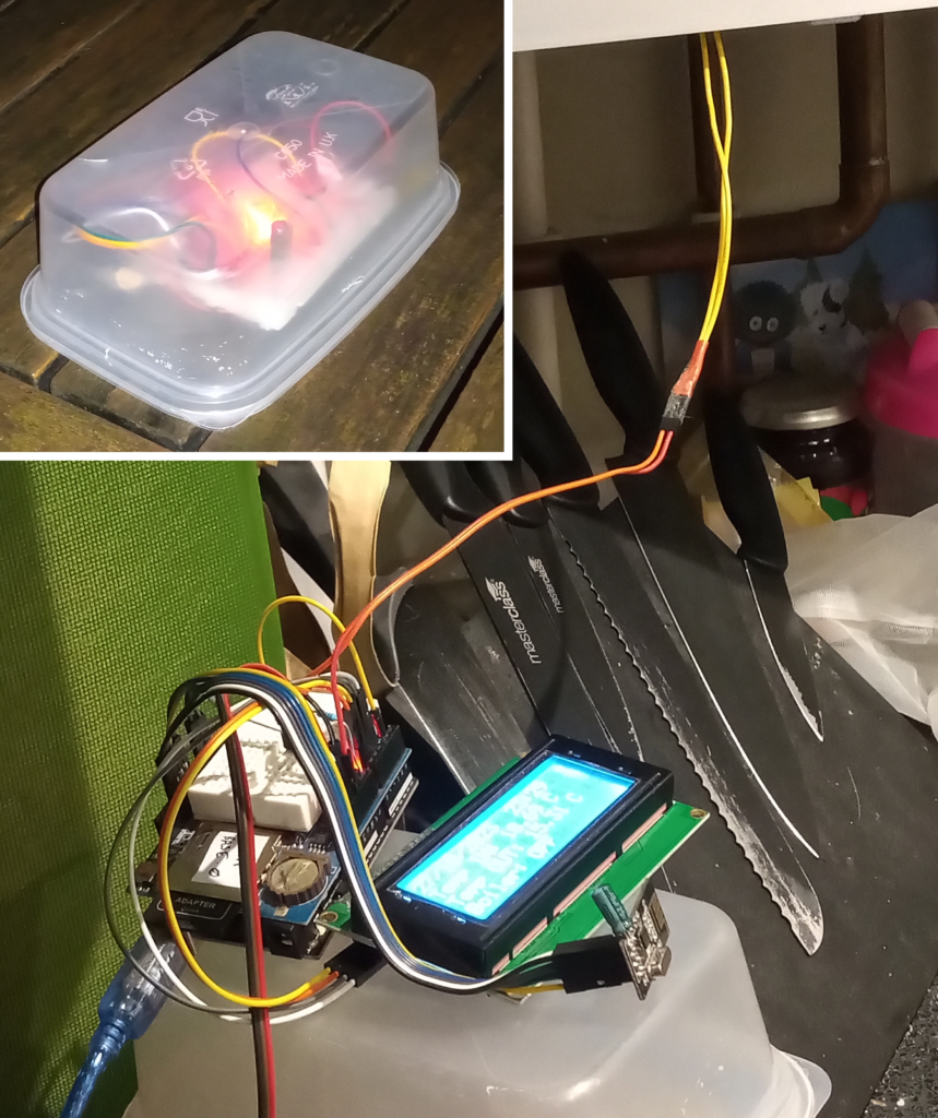
There are two discrete and different parts to the hardware: the external transmitter and the internal receiver and datalogger.
Receiver & Datalogger
Apparently, the logic level converter on the SD card module muddles with the SPI bus in such a way that prevents a nRF24L01 transceiver from working.
The best thing to do when you can’t solve a problem is to redefine the problem. As such, the only way I was able circumvent the problem was to rebuild the setup using a datalogging shield. I don’t know why this works, it just does.
Unfortunately this solution comes with a compromise: the RTC(real time clock). The datalogging shield uses the less accurate DS1302 RTC rather than the temperature compensated DS3231. (Hmm… I wonder if it’s possible to connect the DS3231 to the datalogger….)
Anyway, the setup consisted of:
- Arduino Uno
- Datalogging shield + SD card + coil cell battery
- DS18b20 temperature sensor + 4.7k Ohm resistor
- 20×4 LCD with I2C converter
- nRF24L01 radio module
- 5mm LDR + 10k Ohm resistor.
Add a few jump leads, some blu-tac and a couple of pin headers, then just scream at it until the atoms vibrate into the correct place. Apart from that, you’ll have to piece it together using some imagination and blind faith as I have no schematic.
If you genuinely want to know how to make this then message me via the contact me page and I’ll send some more details to you.
External transmitter
Let’s be honest, the cheap-tupperware-container method of building external sensors is a successful tried-and-tested chassis design used in both the multi-sensor project and the weather station project.
Therefore, if it ain’t broke then don’t fix it, so the set up was the typical:
- Arduino Nano & 300 point breadboard
- DS18b20 temperature sensor + 4.7k Ohm resistor
- nRF24L01 radio module
- 8000mAh 3.7V Li-Po cell with a CN3065 solar charge board (sans solar panel)
- 5V boost board
I’m not sure if the battery control board has a under-voltage protection circuit for the battery. My current plan is to fuck-about-and-find-out. I appreciate the risks involved; yes I know the table might catch fire.
Code
Reciever / Datalogger
Having two lots of hardware necessitates the requirement for two lots of code, and this equals four times the number of headaches.
Below is the code which utilises 9 libraries to control the 6 components over 4 different data busses. I’ve done the screaming so that you don’t have to.
#include <SPI.h>
#include <nRF24L01.h>
#include <RF24.h>
#include <Wire.h>
#include <LiquidCrystal_I2C.h>
#include <SD.h>
#include "RTClib.h"
#include <OneWire.h>
#include <DallasTemperature.h>

#define ONE_WIRE_BUS 2

OneWire oneWire(ONE_WIRE_BUS);
DallasTemperature sensors(&oneWire);

RF24 radio(7, 8); // CE, CSN

LiquidCrystal_I2C lcd(0x27, 20, 4);
RTC_DS1307 rtc;
File dataFile;


const int LDR_pin = A3;
const int chipSelect = 10;
char daysOfTheWeek[7][4] = {"Sun", "Mon", "Tue", "Wed", "Thu", "Fri", "Sat"};
const byte address[] = "00001";
float value[] = {0};
long rxTime = 0;
long refreshRate = 60000;
float outsideTemp;

byte online[8] =
{
  0b00000,
  0b01110,
  0b10001,
  0b00100,
  0b01010,
  0b00000,
  0b00100,
  0b00000
};

byte offline[8] =
{
  0b00000,
  0b10001,
  0b01010,
  0b00100,
  0b00100,
  0b01010,
  0b10001,
  0b00000
};

//***************************************************
void setup() {

  Serial.begin(9600);

  sensors.begin();
  sensors.setResolution(12);

  pinMode(LDR_pin, INPUT);

  lcd.init();
  lcd.backlight();
  lcd.createChar(0, online);
  lcd.createChar(1, offline);

  if (!SD.begin(chipSelect)) {
    lcd.setCursor(0, 0);
    lcd.print("SD card failed");
    while (1) ;
  } // end of if !SD.begin

  dataFile = SD.open("datalog.txt", FILE_WRITE);

  if (! dataFile) {
    lcd.setCursor(0, 0);
    lcd.print("Can't write data");
    while (1) ;
  } // end of if !dataFile

  if (! rtc.begin()) {
    lcd.setCursor(0, 0);
    lcd.print("RTC failed");
    while (1);
  } // end of if !rtc.begin

  rtc.adjust(DateTime(F(__DATE__), F(__TIME__)));   //updates to most current date & time

  radio.begin();

  if (!radio.begin()) {
    lcd.setCursor(0, 0);
    lcd.print("Radio failed");
    while (1) {}
  } // end of if !radio.begin

  radio.setAutoAck(false);
  radio.setChannel(115);
  radio.setPALevel(RF24_PA_MAX);
  radio.openReadingPipe(1, address);
  radio.startListening();
  bool result = radio.isChipConnected();
}
// ************************************************
void loop() {

  //GET DATE & TIME
  DateTime now = rtc.now();

  //DISPLAY DATE & TIME ON LCD
  lcd.clear();
  lcd.setCursor(0, 0);
  lcd.print("  /  /        :  ");    //set up date/time format for top line
  lcd.setCursor(0, 0);
  lcd.print(now.day());
  lcd.setCursor(3, 0);
  lcd.print(now.month());
  lcd.setCursor(6, 0);
  lcd.print(now.year());
  lcd.setCursor(12, 0);
  lcd.print(now.hour());
  lcd.setCursor(15, 0);
  lcd.print(now.minute());

  //ONLINE / OFFLINE MONITOR
  if (rxTime + refreshRate < millis()) {  //out of bounds
    lcd.setCursor(19, 0);
    lcd.write(1);  // writes offline character
  } else {
    lcd.setCursor(19, 0);
    lcd.write(0);  // writes online character
  }

  //GET INSIDE TEMPERATURE FROM DS18B20 & PRINT TO SERIAL
  sensors.requestTemperatures();
  float insideTemp = sensors.getTempCByIndex(0);
  Serial.print("inside temp: ");
  Serial.println(insideTemp);

  //GET BOILER STATUS
  bool boilerStatus;
  int LDR_value = analogRead(LDR_pin);
  if (LDR_value > 100) {
    boilerStatus = true;
  } else {
    boilerStatus = false;
  }

  //RETREIVE MESSAGES FROM RADIO
  if (radio.available()) {
    float value = 0.00;
    radio.read(&value, sizeof(value));
    rxTime = millis();
    outsideTemp = value;
    Serial.print("NEW TRANSMISSION: ");
    Serial.println(value);
  }

  //DISPLAY ON LCD
  lcd.setCursor(0, 1);
  lcd.print("Temp IN: ");
  lcd.print(insideTemp);
  lcd.print(" C");
  lcd.setCursor(0, 2);
  lcd.print("Temp OUT: ");
  lcd.print(outsideTemp);
  lcd.print(" C");
  lcd.setCursor(0, 3);
  lcd.print("Boiler: ");
  if (boilerStatus) {
    lcd.print("ON");
  } else {
    lcd.print("OFF");
  }

  //WRITE TO SD CARD
  String dataString = "";
  dataString += String(now.year(), DEC);
  dataString += String('/');
  dataString += String(now.month(), DEC);
  dataString += String('/');
  dataString += String(now.day(), DEC);
  dataString += String(", ");
  dataString += String(now.hour(), DEC);
  dataString += String(':');
  dataString += String(now.minute(), DEC);
  dataString += String(':');
  dataString += String(now.second(), DEC);
  dataString += String(", ");
  dataString += String(insideTemp);
  dataString += String(", ");
  dataString += String(outsideTemp);
  dataString += String(", ");
  if (boilerStatus) {
    dataString += String("ON");
  } else {
    dataString += String("OFF");
  }
  dataFile.println(dataString);
  dataFile.flush();

  delay(5000);    //5 second refresh
}
Please note: you’ll need to do your own calibration to find the threshold for the LDR on your boiler status light. For my Worcester combi boiler, the analogRead() function returned less than 10 then the boiler was off and between 117-133 when the boiler was on.
External transmitter
I’m not going to lie; this section of code was a 5-minute bastardisation of a previous file from the multi-sensor project. The setup sends a measurement, goes to sleep for 32 seconds and repeats until the battery is flat; a metaphor for my life, really.
#include <LowPower.h>
#include <OneWire.h>
#include <DallasTemperature.h>
#include <SPI.h>
#include <nRF24L01.h>
#include <RF24.h>

#define ONE_WIRE_BUS 2

OneWire oneWire(ONE_WIRE_BUS);
DallasTemperature sensors(&oneWire);
RF24 radio(7, 8); // CE, CSN

const byte address[] = "00001";
float temp;

//******************************************
void setup() {
  Serial.begin(9600);
  sensors.begin();
  sensors.setResolution(12);

  radio.begin();
  if (!radio.begin()) {
    Serial.println(F("radio hardware not responding!"));
    while (1);
  }
  radio.setAutoAck(false);
  radio.setChannel(115);
  radio.setPALevel(RF24_PA_LOW);
  radio.openWritingPipe(address);
  radio.stopListening();
}
//******************************************
void loop() {
  sendMeasure();
  goToSleep(4);   //pass number of 8 second sleeps , 4 * 8 = 32s refresh
}
//******************************************
void goToSleep(int i_) {
  for (int i = 0; i < i_; i++) {
    LowPower.powerDown(SLEEP_8S, ADC_OFF, BOD_OFF);
  }
}
//******************************************
void sendMeasure() {
  sensors.requestTemperatures();
  float inTemp = sensors.getTempCByIndex(0);
  radio.write(&inTemp, sizeof(inTemp));
  Serial.println(inTemp);
  delay(1000);
}
Results & Findings
If I wanted to go bug hunting then I would have studied entomology rather than electronics. This project took over 7 days to complete due to the sheer number of bugs discovered.
The test was started on 27/10/2023 and as of 30/10/2023 the test is still collecting data. The duration of the test is ultimately governed by the battery in the external transmitter; assuming a generous power consumption of 31.3mAh gives approx. 10 days usage. Test.
However, my craving for sweet, sweet data (and the risk of under-volting a sizeable Li-Po) might call time after a week. Results and findings will be posted here when I have them.
Thank you for reading; all questions welcomed.
Page created: 29/10/2023
Last updated: 30/10/2023