This is a quick run through on how to use the GC9A01 round TFT display with your bog standard Arduino. In this case I’m using a nano, however, the same will work with an Uno (and Mega2560 if you change the pin numbers).
If you want to connect this display with an ESP32 then check out this write-up. Or if you want to wire this up to an ESP32-CAM to display your beautiful face through a TFT porthole, then see this write-up and then this subsequent upgrade.
Hardware
NOTE: The display uses 3.3V power and logic.
5V will likely bugger the display; I’ve not confirmed this myself.
Logic Level converter
You will need a logic level converter to communicate with the 5V Arduino; don’t bother fucking about with resistors and voltage divider circuits.
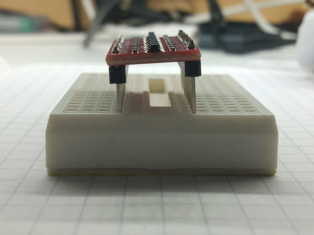
The logic level converter that came with the display is pictured to the right; however, after soldering it was noted that the pin spacing didn’t suit standard 0.1″ pitch breadboards.
As such, I opted for the HW-221 8-channel bi-directional logic level converter based on the TXS0108E chip.
Pinouts
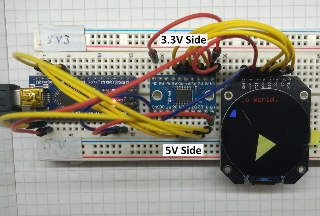
Refer to the photo above for a rough idea on layout; the ‘A’ side of the logic level converter is on the 3V3 side and the ‘B’ side of the logic level converter is on the 5V side.
However, to remove any doubt, the pinout is as follows:
- HW-221 GND -> Arduino GND & GC9A01 GND
- HW-221 VA -> Arduino 3.3V & GC9A01 VCC
- HW-221 A1 -> GC9A01 SCL
- HW-221 A2 -> GC9A01 SDA
- HW-221 A3 -> GC9A01 RES
- HW-221 A4 -> GC9A01 DC
- HW-221 A5 -> GC9A01 CS
- HW-221 OE (output enable) -> Arduino 3.3V (active high)
- HW-221 VB -> Arduino 5V
- HW-221 B1 -> Arduino D13
- HW-221 B2 -> Arduino D11
- HW-221 B3 -> Arduino D8
- HW-221 B4 -> Arduino D9
- HW-221 B5 -> Arduino D10
If that was confusing then hopefully this helps:
- GC9A01 SCL -[via converter]-> Arduino D13 (SPI clock)
- GC9A01 SDA -[via converter]-> Arduino D11 (SPI MOSI)
- GC9A01 RES-[via converter]-> Arduino D8
- GC9A01 DC -[via converter]-> Arduino D9
- GC9A01 CS-[via converter]-> Arduino D10 (SPI chip select)
Software
For this setup, I used the Adafruit GFX base library, with the Adafruit_GC9A01A.h library. Within that library there is a graphics test example which should produce the following spectacle of geometric colours
If you want some copy and paste code then the below will produce the same test image as the header photo above. Note that although this is a 240×240 pixel display; that’s only across the centre.
/*
 * GC9A01 ROUND LCD DISPLAY
 *
 * 08/06/2024
 *
 * Pinout:
 *
 * CS > Logic level converter > D10
 * DC > Logic level converter > D9
 * RES > Logic level converter > D8
 * SDA > Logic level converter > D11
 * SCL > Logic level converter > D13
 * VCC > 3.3V
 * GND > GND
 *
 */

#include "SPI.h"
#include "Adafruit_GFX.h"
#include "Adafruit_GC9A01A.h"

#define TFT_DC  9
#define TFT_CS 10

Adafruit_GC9A01A tft(TFT_CS, TFT_DC);

void setup() {
  tft.begin();
  tft.fillScreen(GC9A01A_BLACK);      //equivalent to clear screen
  tft.setTextColor(GC9A01A_WHITE);
}

void loop() {
  tft.setCursor(10, 0);
  tft.setTextSize(1);
  tft.print("Hello World.");
  tft.setCursor(10, 12);
  tft.setTextSize(2);
  tft.setTextColor(GC9A01A_RED);
  tft.print("Hello World.");
  tft.drawLine(50, 50, 75, 90, GC9A01A_GREEN);
  tft.fillRect(10, 50, 20, 20, GC9A01A_BLUE);
  tft.fillTriangle(100 , 120, 150, 150, 90, 200, GC9A01A_YELLOW);
  while (1);
}
Best of luck!
Page created: 22/06/2024
Page last edited: 22/06/2024