As requested via the contact page, this is a short write-up on how to interface the AI-Thinker ESP32CAM and 5MP OV5640 camera sensor with a GC9A01 display.
This particular sensor has the 68 degree lens and 21mm long ribbon cable.
This request also spurred the idea for the digital panning experiment, which windows a larger camera frame and uses a joystick to move the window within the camera frame.

Hardware
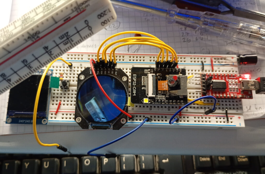
This setup is an identical copy to the original GC9A01 camera setup, but to assist in the wiring, the connections are as follows.
- GC9A01 GND -> ESP32-CAM GND
- GC9A01 VCC -> ESP32-CAM 3.3V
- GC9A01 SCL-> ESP32-CAM GPIO 14
- GC9A01 SDA -> ESP32-CAM GPIO 13
- GC9A01 RES -> ESP32-CAM GPIO 15
- GC9A01 DC -> ESP32-CAM GPIO 12
- GC9A01 CS -> ESP32-CAM GPIO 2
- GC9A01 BLK -> [not connected]
Software – User_Setup.h
When compiling the sketch, the User_Setup.h file in the TFT_eSPI library needs to be the following:
#define USER_SETUP_INFO "User_Setup"
#define GC9A01_DRIVER
#define TFT_SDA_READ      // This option is for ESP32 ONLY, tested with ST7789 and GC9A01 display only
#define TFT_HEIGHT 240 // GC9A01 240 x 240
#define TFT_MOSI 13 // In some display driver board, it might be written as "SDA" and so on.
#define TFT_SCLK 14
#define TFT_CS   2  // Chip select control pin
#define TFT_DC   12  // Data Command control pin
#define TFT_RST  15  // Reset pin (could connect to Arduino RESET pin)
#define TOUCH_CS 21     // Chip select pin (T_CS) of touch screen
#define LOAD_GLCD   // Font 1. Original Adafruit 8 pixel font needs ~1820 bytes in FLASH
#define LOAD_FONT2  // Font 2. Small 16 pixel high font, needs ~3534 bytes in FLASH, 96 characters
#define LOAD_FONT4  // Font 4. Medium 26 pixel high font, needs ~5848 bytes in FLASH, 96 characters
#define LOAD_FONT6  // Font 6. Large 48 pixel font, needs ~2666 bytes in FLASH, only characters 1234567890:-.apm
#define LOAD_FONT7  // Font 7. 7 segment 48 pixel font, needs ~2438 bytes in FLASH, only characters 1234567890:-.
#define LOAD_FONT8  // Font 8. Large 75 pixel font needs ~3256 bytes in FLASH, only characters 1234567890:-.
#define LOAD_GFXFF  // FreeFonts. Include access to the 48 Adafruit_GFX free fonts FF1 to FF48 and custom fonts
#define SMOOTH_FONT
#define SPI_FREQUENCY  40000000
#define SPI_READ_FREQUENCY  20000000
#define SPI_TOUCH_FREQUENCY  2500000
#define USE_HSPI_PORT
#define SUPPORT_TRANSACTIONS
If you do not get a “loading” screen on your display, then it’s likely that there is an issue with the setup. Reducing the SPI_FREQUENCY to 27000000 can help, but it will negatively impact the refresh rate of your display.
Software – Main Sketch
Again, this uses the same code from the previous experiment, but for ease, it is included in full below.
Please note that this uses the dual core functionality of ESP32-S. Lesser models will likely crap out if they don’t have the second CPU core. The single core code can be found here.
#include "esp_camera.h"
#include <TFT_eSPI.h> // Hardware-specific library
#include <SPI.h>

#define CAMERA_MODEL_AI_THINKER
#define PWDN_GPIO_NUM     32
#define RESET_GPIO_NUM    -1
#define XCLK_GPIO_NUM      0
#define SIOD_GPIO_NUM     26
#define SIOC_GPIO_NUM     27
#define Y9_GPIO_NUM       35
#define Y8_GPIO_NUM       34
#define Y7_GPIO_NUM       39
#define Y6_GPIO_NUM       36
#define Y5_GPIO_NUM       21
#define Y4_GPIO_NUM       19
#define Y3_GPIO_NUM       18
#define Y2_GPIO_NUM        5
#define VSYNC_GPIO_NUM    25
#define HREF_GPIO_NUM     23
#define PCLK_GPIO_NUM     22

TaskHandle_t Task1;

TFT_eSPI tft = TFT_eSPI();       // Invoke custom library
TFT_eSprite spr = TFT_eSprite(&tft);

camera_config_t config;

uint16_t *scr;
long initalTime = 0;
long frameTime = 1;
volatile bool screenRefreshFlag = true;

/////////////////////////////////
void Task1code( void * pvParameters ) {
  //core0 setup
  config.ledc_channel = LEDC_CHANNEL_0;
  config.ledc_timer = LEDC_TIMER_0;
  config.pin_d0 = Y2_GPIO_NUM;
  config.pin_d1 = Y3_GPIO_NUM;
  config.pin_d2 = Y4_GPIO_NUM;
  config.pin_d3 = Y5_GPIO_NUM;
  config.pin_d4 = Y6_GPIO_NUM;
  config.pin_d5 = Y7_GPIO_NUM;
  config.pin_d6 = Y8_GPIO_NUM;
  config.pin_d7 = Y9_GPIO_NUM;
  config.pin_xclk = XCLK_GPIO_NUM;
  config.pin_pclk = PCLK_GPIO_NUM;
  config.pin_vsync = VSYNC_GPIO_NUM;
  config.pin_href = HREF_GPIO_NUM;
  config.pin_sscb_sda = SIOD_GPIO_NUM;
  config.pin_sscb_scl = SIOC_GPIO_NUM;
  config.pin_pwdn = PWDN_GPIO_NUM;
  config.pin_reset = RESET_GPIO_NUM;
  config.xclk_freq_hz = 20000000;
  config.frame_size = FRAMESIZE_240X240;
  config.pixel_format = PIXFORMAT_RGB565;
  config.grab_mode = CAMERA_GRAB_LATEST;    //option CAMERA_GRAB_WHEN_EMPTY
  config.fb_location = CAMERA_FB_IN_PSRAM;
  config.jpeg_quality = 12;
  config.fb_count = 2;                          //need more than 1 for latest grab

  esp_err_t err = esp_camera_init(&config);
  sensor_t * s = esp_camera_sensor_get();
  s->set_brightness(s, 0);     // -2 to 2
  s->set_contrast(s, 0);       // -2 to 2
  s->set_saturation(s, 0);     // -2 to 2
  s->set_special_effect(s, 0); // 0 to 6 (0 - No Effect, 1 - Negative, 2 - Grayscale, 3 - Red Tint, 4 - Green Tint, 5 - Blue Tint, 6 - Sepia)
  s->set_whitebal(s, 1);       // 0 = disable , 1 = enable
  s->set_awb_gain(s, 1);       // 0 = disable , 1 = enable
  s->set_wb_mode(s, 0);        // 0 to 4 - if awb_gain enabled (0 - Auto, 1 - Sunny, 2 - Cloudy, 3 - Office, 4 - Home)
  s->set_exposure_ctrl(s, 1);  // 0 = disable , 1 = enable
  s->set_aec2(s, 0);           // 0 = disable , 1 = enable
  s->set_ae_level(s, 0);       // -2 to 2
  s->set_aec_value(s, 300);    // 0 to 1200
  s->set_gain_ctrl(s, 1);      // 0 = disable , 1 = enable
  s->set_agc_gain(s, 0);       // 0 to 30
  s->set_gainceiling(s, (gainceiling_t)0);  // 0 to 6
  s->set_bpc(s, 0);            // 0 = disable , 1 = enable
  s->set_wpc(s, 1);            // 0 = disable , 1 = enable
  s->set_raw_gma(s, 1);        // 0 = disable , 1 = enable
  s->set_lenc(s, 1);           // 0 = disable , 1 = enable
  s->set_hmirror(s, 0);        // 0 = disable , 1 = enable
  s->set_vflip(s, 0);          // 0 = disable , 1 = enable
  s->set_dcw(s, 1);            // 0 = disable , 1 = enable
  s->set_colorbar(s, 0);       // 0 = disable , 1 = enable

  //core0 loop
  for (;;) {
    //take picture
    camera_fb_t  * fb = NULL;
    fb = esp_camera_fb_get();
    //transfer frame buffer data to pointer
    for (size_t i = 0; i < 57600; i++) {    //240x240px = 57600
      byte first_byte = fb->buf[i * 2];
      byte second_byte = fb->buf[i * 2 + 1];
      scr[i] = (second_byte << 8) + first_byte;
    }
    screenRefreshFlag = true;
    esp_camera_fb_return(fb);   //return the frame buffer back to the driver for reuse
  }
}

//////////////////////////////////////////////////////////
void setup() {

  tft.init();
  tft.setRotation(0);
  tft.fillScreen(TFT_BLACK);
  tft.setTextColor(TFT_BLACK, TFT_WHITE);
  scr = (uint16_t*)spr.createSprite(240, 240);
  tft.drawString("Loading...", 105, 105, 2);

  xTaskCreatePinnedToCore(
    Task1code,   // Task function.
    "Task1",     // name of task.
    100000,      // Stack size of task
    NULL,        // parameter of the task
    1,           // priority of the task
    &Task1,      // Task handle to keep track of created task
    0);          // pin task to core 0

  delay(1000);
}

//////////////////////////////////
void loop() {
  //refresh display if there is a new image from the camera
  if (screenRefreshFlag) {
    initalTime = millis();
    spr.drawString(String(frameTime), 100, 220, 2); //print frame time in milliseconds
    spr.drawString("ms", 125, 220, 2);
    spr.pushSprite(0, 0);
    screenRefreshFlag = false;
    frameTime = millis() - initalTime;
  }
}
All being well, once the sketch is compiled, uploaded and the device is reset, you should get the following result:
Troubleshooting
While trying this setup I encountered two main problems.
Problem #1 – Brownout
This issue shows itself as a dim display coupled with the RX/TX light on the FTDI flashing. You can confirm that it’s a brownout by opening the serial monitor and you’ll see the below
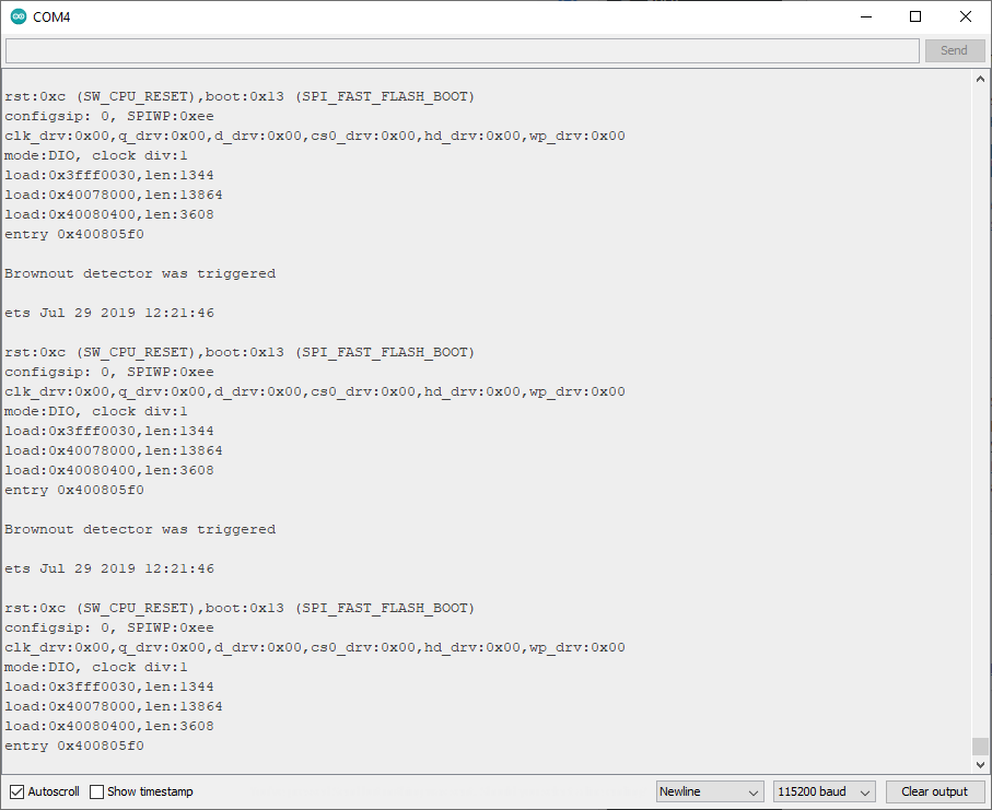
To solve this I simply held a flying ground pin to the GND/R pin (closest to the LED flash) for about 3 seconds before releasing. I’m guessing that this gives suitable time for the capacitors to charge.
Problem #2 – Thermal Runaway
I’m unsure if this problem is common amoungst all of the OV5640 sensors, but this one got very hot, very fast. The image below shows a 60.5 degree C temperature coming from the sensor.
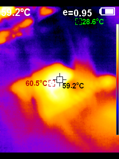
This will need a heatsink or other form of active cooling to prevent overheating as the datasheet notes that the stable picture temperature maxes out at 50 degrees C.