This is a guide for how to show a live video stream from the OV2640 camera module attached to an AI-Thinker ESP32-CAM on a 1.28inch 240x240pixel circular TFT display.
Refresh rates as low as 19-20ms (50-52.6 FPS) can be achieved on the display; however, the camera cannot keep up so fast motion results in a rolling-blur.
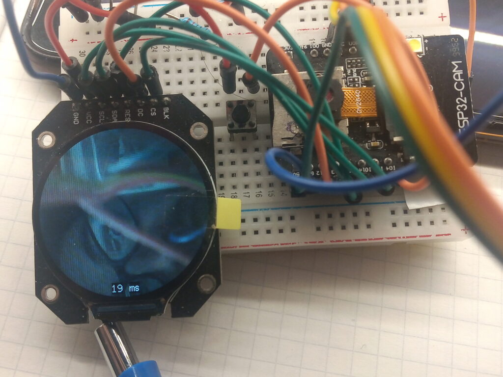
This guide makes the assumption that you’re familiar with the ESP32CAM and the nuances of the uploading procedure.
Hardware
The display used here is a GC9A01 circular TFT LCD screen. The MCU is an ESP32-CAM (AI-Thinker). Programming via an FTDI TTL Serial adapter.
There are two large hardware-based caveats with setup; the first is that the pins used for the display are typically used for the SD card. As such, this setup cannot record video data. (That’s not to say it cannot be done, but I cannot be arsed to try).
Secondly; the code uses both cores of the CPU. If your MCU is a single core processor then this code might not work. I’ve still been able to achieve 12.5 FPS with a single core (code for this can be found in a hidden post here).
The pinout for the display is as follows:
- GC9A01 GND -> ESP32-CAM GND
- GC9A01 VCC -> ESP32-CAM 3.3V
- GC9A01 SCL-> ESP32-CAM GPIO 14
- GC9A01 SDA -> ESP32-CAM GPIO 13
- GC9A01 RES -> ESP32-CAM GPIO 15
- GC9A01 DC -> ESP32-CAM GPIO 12
- GC9A01 CS -> ESP32-CAM GPIO 2
- GC9A01 BLK -> [not connected]
This photo shows the indicative setup used. If you get flickering then add a large capacitor on the power pins (> 100uF 25V). However, do not use GPIO 16 for anything. I’ve found that it causes errors when used as an input or output.
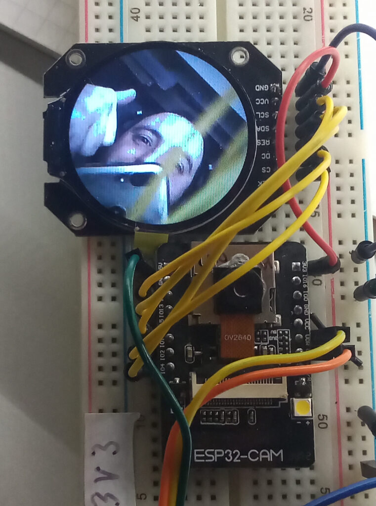
The other connections are to the FTDI adapter which are as follows:
- ESP32-CAM GND -> FTDI GND
- ESP32-CAM 5V -> FTDI VCC (note: the voltage jumper on the adapter should be to the 5V pin)
- ESP32-CAM UOR -> FTDI TX
- ESP32-CAM UOT -> FTDI RX
Note: you’ll need to connect GPIO 0 of the ESP32-CAM to GND to enable ‘flashing mode’ in order to upload your code. Once the program has been uploaded, this connection needs to be removed and the ESP32-CAM restarted.
Hint: Use a flying ground lead to touch against the GND/R pin to reset the ESP32.
Software: User_Setup.h
As always, this setup uses the TFT_eSPI library by Bodmer. Therefore, when when compiling the main sketch; the User_Setup.h file in the library folder must be configured correctly to work with the GC9A01 display driver.
These are the necessary settings; just simply CTRL+A, then CTRL+C, open the file, CTRL+V and CTRL+S. Easy.
#define USER_SETUP_INFO "User_Setup"
#define GC9A01_DRIVER
#define TFT_SDA_READ      // This option is for ESP32 ONLY, tested with ST7789 and GC9A01 display only
#define TFT_HEIGHT 240 // GC9A01 240 x 240
#define TFT_MOSI 13 // In some display driver board, it might be written as "SDA" and so on.
#define TFT_SCLK 14
#define TFT_CS   2  // Chip select control pin
#define TFT_DC   12  // Data Command control pin
#define TFT_RST  15  // Reset pin (could connect to Arduino RESET pin)
#define TOUCH_CS 21     // Chip select pin (T_CS) of touch screen
#define LOAD_GLCD   // Font 1. Original Adafruit 8 pixel font needs ~1820 bytes in FLASH
#define LOAD_FONT2  // Font 2. Small 16 pixel high font, needs ~3534 bytes in FLASH, 96 characters
#define LOAD_FONT4  // Font 4. Medium 26 pixel high font, needs ~5848 bytes in FLASH, 96 characters
#define LOAD_FONT6  // Font 6. Large 48 pixel font, needs ~2666 bytes in FLASH, only characters 1234567890:-.apm
#define LOAD_FONT7  // Font 7. 7 segment 48 pixel font, needs ~2438 bytes in FLASH, only characters 1234567890:-.
#define LOAD_FONT8  // Font 8. Large 75 pixel font needs ~3256 bytes in FLASH, only characters 1234567890:-.
#define LOAD_GFXFF  // FreeFonts. Include access to the 48 Adafruit_GFX free fonts FF1 to FF48 and custom fonts
#define SMOOTH_FONT
#define SPI_FREQUENCY  40000000
#define SPI_READ_FREQUENCY  20000000
#define SPI_TOUCH_FREQUENCY  2500000
#define USE_HSPI_PORT
#define SUPPORT_TRANSACTIONS
If you have reliability issues then change the SPI_FREQUENCY from 40000000 down to 27000000; however, this will impact the refresh time. I’ve tested the following:
- #define SPI_FREQUENCY 27000000 // 42ms refresh = 23.8 FPS
- #define SPI_FREQUENCY 40000000 // 31ms refresh = 32.3 FPS
- #define SPI_FREQUENCY 80000000 // 20ms refresh = 50.0 FPS
You could also probably trim the fonts and touch out of the code to save some space; but they ain’t harming anyone.
Software – Main Sketch
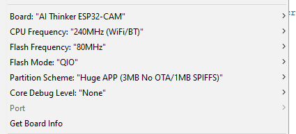
Once again, employ the use of CTRL+C and CTRL+V to purloin the code. Then simply plug in your FTDI adapter, and connect GPIO 0 to GND, compile and upload. The following board settings have been used; take note of the flash mode being QIO and partition scheme being HUGE APP.
#include "esp_camera.h"
#include <TFT_eSPI.h> // Hardware-specific library
#include <SPI.h>

#define CAMERA_MODEL_AI_THINKER
#define PWDN_GPIO_NUM     32
#define RESET_GPIO_NUM    -1
#define XCLK_GPIO_NUM      0
#define SIOD_GPIO_NUM     26
#define SIOC_GPIO_NUM     27
#define Y9_GPIO_NUM       35
#define Y8_GPIO_NUM       34
#define Y7_GPIO_NUM       39
#define Y6_GPIO_NUM       36
#define Y5_GPIO_NUM       21
#define Y4_GPIO_NUM       19
#define Y3_GPIO_NUM       18
#define Y2_GPIO_NUM        5
#define VSYNC_GPIO_NUM    25
#define HREF_GPIO_NUM     23
#define PCLK_GPIO_NUM     22

TaskHandle_t Task1;

TFT_eSPI tft = TFT_eSPI();       // Invoke custom library
TFT_eSprite spr = TFT_eSprite(&tft);

camera_config_t config;

uint16_t *scr;
long initalTime = 0;
long frameTime = 1;
volatile bool screenRefreshFlag = true;

/////////////////////////////////
void Task1code( void * pvParameters ) {
  //core0 setup
  config.ledc_channel = LEDC_CHANNEL_0;
  config.ledc_timer = LEDC_TIMER_0;
  config.pin_d0 = Y2_GPIO_NUM;
  config.pin_d1 = Y3_GPIO_NUM;
  config.pin_d2 = Y4_GPIO_NUM;
  config.pin_d3 = Y5_GPIO_NUM;
  config.pin_d4 = Y6_GPIO_NUM;
  config.pin_d5 = Y7_GPIO_NUM;
  config.pin_d6 = Y8_GPIO_NUM;
  config.pin_d7 = Y9_GPIO_NUM;
  config.pin_xclk = XCLK_GPIO_NUM;
  config.pin_pclk = PCLK_GPIO_NUM;
  config.pin_vsync = VSYNC_GPIO_NUM;
  config.pin_href = HREF_GPIO_NUM;
  config.pin_sscb_sda = SIOD_GPIO_NUM;
  config.pin_sscb_scl = SIOC_GPIO_NUM;
  config.pin_pwdn = PWDN_GPIO_NUM;
  config.pin_reset = RESET_GPIO_NUM;
  config.xclk_freq_hz = 20000000;
  config.frame_size = FRAMESIZE_240X240;
  config.pixel_format = PIXFORMAT_RGB565;
  config.grab_mode = CAMERA_GRAB_LATEST;    //option CAMERA_GRAB_WHEN_EMPTY
  config.fb_location = CAMERA_FB_IN_PSRAM;
  config.jpeg_quality = 12;
  config.fb_count = 2;                          //need more than 1 for latest grab

  esp_err_t err = esp_camera_init(&config);
  sensor_t * s = esp_camera_sensor_get();
  s->set_brightness(s, 0);     // -2 to 2
  s->set_contrast(s, 0);       // -2 to 2
  s->set_saturation(s, 0);     // -2 to 2
  s->set_special_effect(s, 0); // 0 to 6 (0 - No Effect, 1 - Negative, 2 - Grayscale, 3 - Red Tint, 4 - Green Tint, 5 - Blue Tint, 6 - Sepia)
  s->set_whitebal(s, 1);       // 0 = disable , 1 = enable
  s->set_awb_gain(s, 1);       // 0 = disable , 1 = enable
  s->set_wb_mode(s, 0);        // 0 to 4 - if awb_gain enabled (0 - Auto, 1 - Sunny, 2 - Cloudy, 3 - Office, 4 - Home)
  s->set_exposure_ctrl(s, 1);  // 0 = disable , 1 = enable
  s->set_aec2(s, 0);           // 0 = disable , 1 = enable
  s->set_ae_level(s, 0);       // -2 to 2
  s->set_aec_value(s, 300);    // 0 to 1200
  s->set_gain_ctrl(s, 1);      // 0 = disable , 1 = enable
  s->set_agc_gain(s, 0);       // 0 to 30
  s->set_gainceiling(s, (gainceiling_t)0);  // 0 to 6
  s->set_bpc(s, 0);            // 0 = disable , 1 = enable
  s->set_wpc(s, 1);            // 0 = disable , 1 = enable
  s->set_raw_gma(s, 1);        // 0 = disable , 1 = enable
  s->set_lenc(s, 1);           // 0 = disable , 1 = enable
  s->set_hmirror(s, 0);        // 0 = disable , 1 = enable
  s->set_vflip(s, 0);          // 0 = disable , 1 = enable
  s->set_dcw(s, 1);            // 0 = disable , 1 = enable
  s->set_colorbar(s, 0);       // 0 = disable , 1 = enable

  //core0 loop
  for (;;) {
    //take picture
    camera_fb_t  * fb = NULL;
    fb = esp_camera_fb_get();
    //transfer frame buffer data to pointer
    for (size_t i = 0; i < 57600; i++) {    //240x240px = 57600
      byte first_byte = fb->buf[i * 2];
      byte second_byte = fb->buf[i * 2 + 1];
      scr[i] = (second_byte << 8) + first_byte;
    }
    screenRefreshFlag = true;
    esp_camera_fb_return(fb);   //return the frame buffer back to the driver for reuse
  }
}

//////////////////////////////////////////////////////////
void setup() {

  tft.init();
  tft.setRotation(0);
  tft.fillScreen(TFT_BLACK);
  tft.setTextColor(TFT_BLACK, TFT_WHITE);
  scr = (uint16_t*)spr.createSprite(240, 240);
  tft.drawString("Loading...", 105, 105, 2);

  xTaskCreatePinnedToCore(
    Task1code,   // Task function.
    "Task1",     // name of task.
    100000,      // Stack size of task
    NULL,        // parameter of the task
    1,           // priority of the task
    &Task1,      // Task handle to keep track of created task
    0);          // pin task to core 0

  delay(1000);
}

//////////////////////////////////
void loop() {
  //refresh display if there is a new image from the camera
  if (screenRefreshFlag) {
    initalTime = millis();
    spr.drawString(String(frameTime), 100, 220, 2); //print frame time in milliseconds
    spr.drawString("ms", 125, 220, 2);
    spr.pushSprite(0, 0);
    screenRefreshFlag = false;
    frameTime = millis() - initalTime;
  }
}
Now remove the connection for GPIO 0, restart the ESP32-CAM and enjoy 240×240 pixel 16-bit quality at 32 FPS.
Troubleshooting
There is a known issue raised in this subreddit thread where the display is not working correctly.
The pinout for some round displays appears to be different in regards to the reset pin. The revised pinout is noted to the right.
This change must also be reflected in the User_Setup.h file, where the pin that defines the reset is changed from:
#define TFT_RST 15To:
#define TFT_RST -1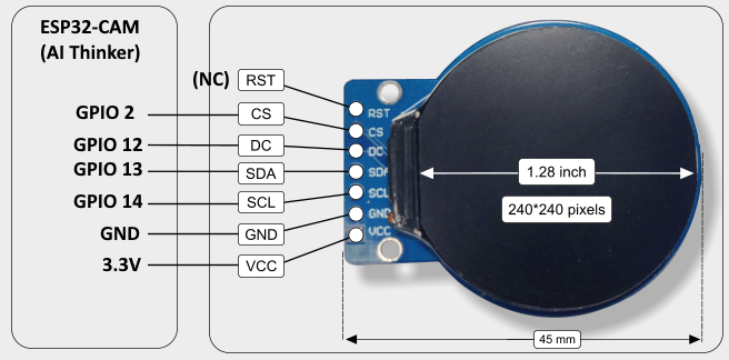
It’s worth noting that this is still an untested solution, as I don’t have access to the specific display.
Therefore, to aid troubleshooting and provide a static test for the display; the following code can be used. To increase reliability (particularly due to long cables), the SPI bus speed should be lowered to 27000000 within the User_Setup.h file.
#include <TFT_eSPI.h>
#include <SPI.h>

TFT_eSPI tft = TFT_eSPI();

void setup() {
  tft.init();
  tft.setRotation(0);
  tft.fillScreen(TFT_BLACK);
  tft.setTextColor(TFT_WHITE);
  tft.drawString("Loading...", 105, 105, 2);
  delay(500);
}

void loop() {

}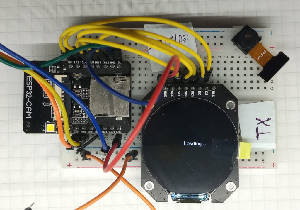
The above test shows the camera module disconnected to verify the display works independently.
If the screen shows “Loading…”, then this is a win.
If you’ve read this far. Thank you. If you have any comments or questions then my inbox is open via the contact page.
Page created: 13/06/2024
Page last edited: 10/02/2025