Background
It was Saturday the 30th of July 2022; the mobility scooter project was struggling with brake problems, and the first test run of the quad project had just failed miserably. At this point the decision was made to take the motor from the mobility scooter and insert it into the chassis of the quad.

Preliminary Checks
The motor, controller, batteries, and wiring loom were all extracted from the mobility scooter.
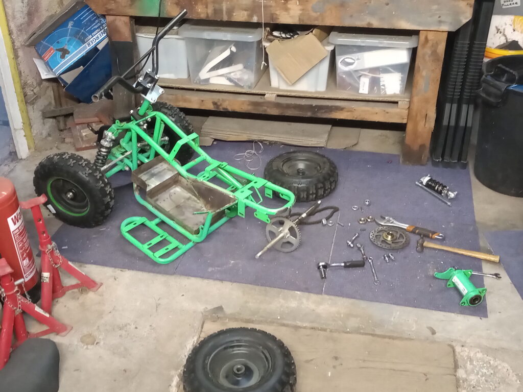
Meanwhile, the quad was completely stripped back to a rolling chassis – the motor, fuel tank and exhaust system where all removed.
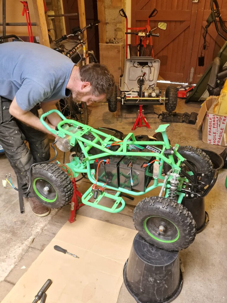
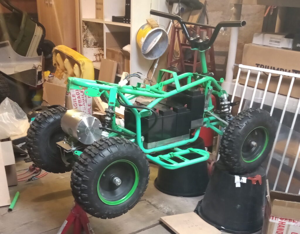
The salvaged parts were then dry fitted into the empty chassis to ensure that there was enough space, and the conversion was viable.
Thankfully the chain used for both projects was the same gauge, so the rear axle sprocket was compatible with the motor.
While the old petrol motor is visible in the mobility scooter, it actually ended up on a pedal kart.
Motor Mount
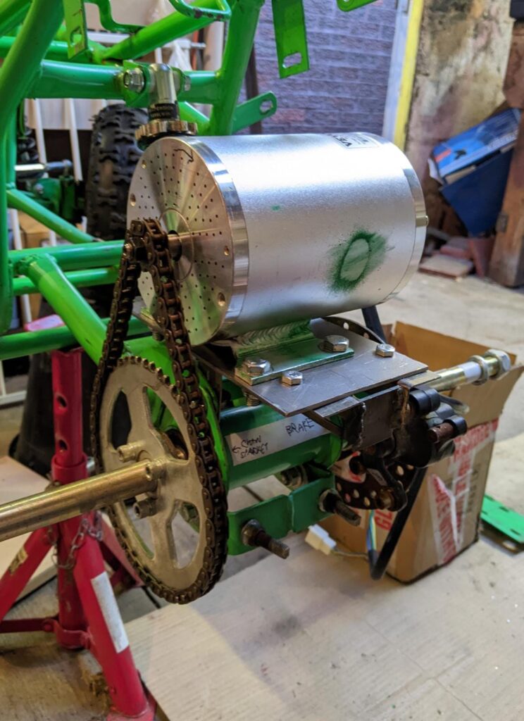
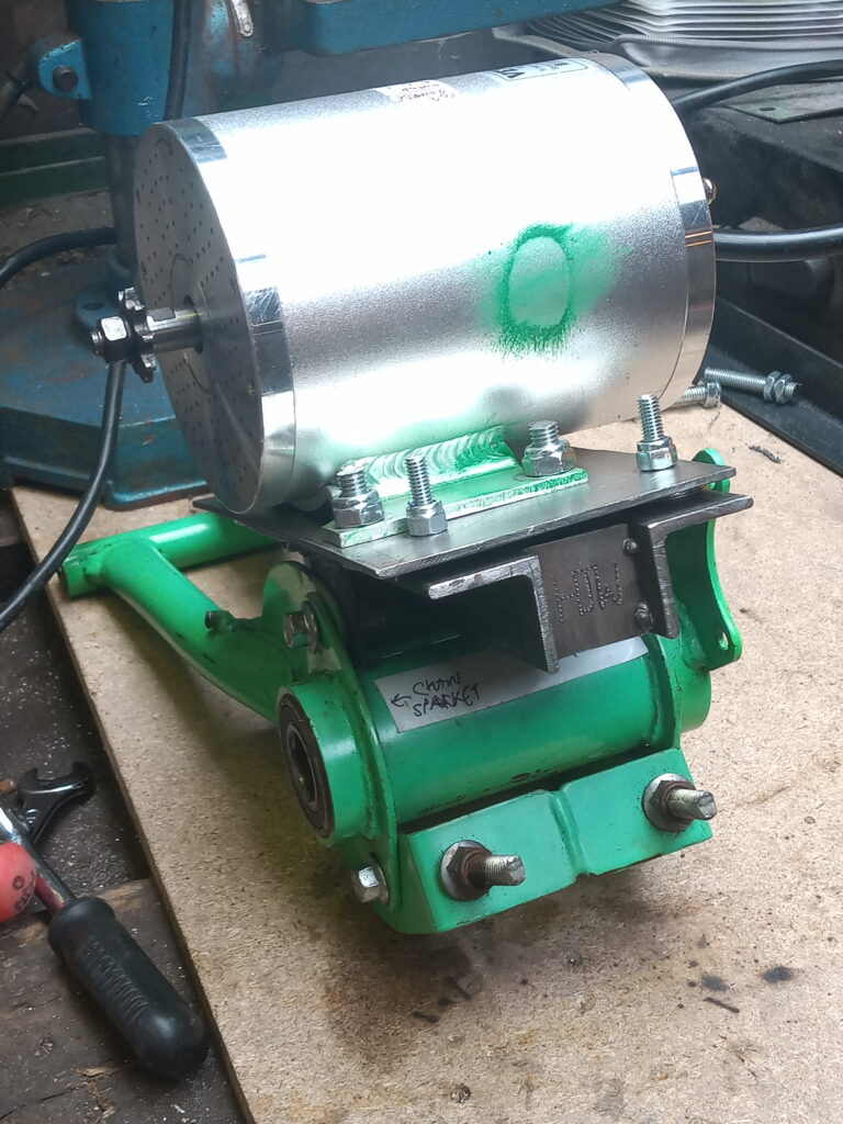
The first job was to design and fabricate a new mount to connect the electric motor with the rear subframe of the quad while keeping the chain aligned with the sprocket.
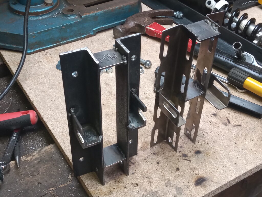
With experience on my side, I knew my first attempt would fail…
…And it did; the slotted steel angle simply wasn’t strong enough and the heat from welding caused it to warp.
However, the overall design was acceptable and only required a new bolt through the lower suspension with no permanent changes to the existing subframe.
The second (and final) version was made with 30x30x2.5mm steel angle and was a lot stiffer.
Electrical – Motor
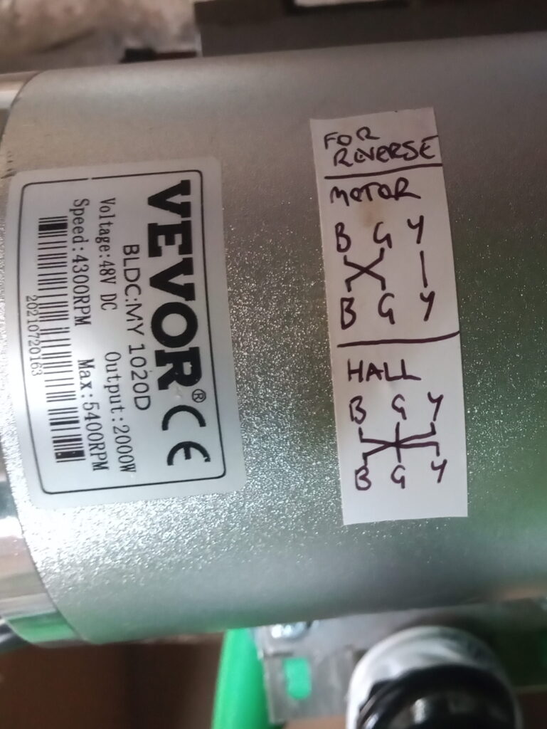
The more eagle eyed of you might have noticed the direction arrow crudely drawn on the face of the motor points backwards. Bugger.

This seemingly innocuous hurdle almost killed the project in the early stages. The answer was found after trawling trough many obscure online forums and testing many (incorrect) configurations.
The successful combination of motor phase and hall effect sensor wires was immortalised on the motor casing using a strip of white electrical tape and a sharpie: proper documentation!
Test Ride 1: Jury Rig
With the stronger motor mount fitted and chain tensioned, a test rig was cobbled together to see how the quad performed.
The resulting jury-rigged death trap was wired to a 48-volt eBike battery with a pair of M3 screws jammed in the terminals.
My feet held the entire contraption together whilst also acting as the brakes. That’s safe, right?
The results were alarming: the motor generated enough torque to cause the quad to wheelie; even with minimal throttle. With the front wheels in the air, the steering response was non-existent, causing massive under-steer.
You can see the exact point I defecate in my pants.
Batteries
The four 12 volt, 22Ah lead acid batteries from the mobility scooter were also transferred over to the quad.
Along with the batteries came the major headache of how to fit them all into the tiny chassis.
A cardboard template of the battery tray was made before being fabricated from 0.7mm sheet steel.
The tolerances between the batteries and chassis were sub-millimetre, and I was surprised to have the battery tray fit first time!
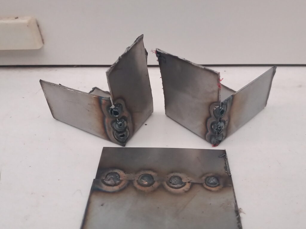
Several test corners were made from off-cuts to dial in the current and voltage settings of the welder.
Even with the minimum settings, the welder would blow a hole through the edge of the sheet steel. Therefore, the corners were fixed with straps and overlapping welds.

Electrical – Controller
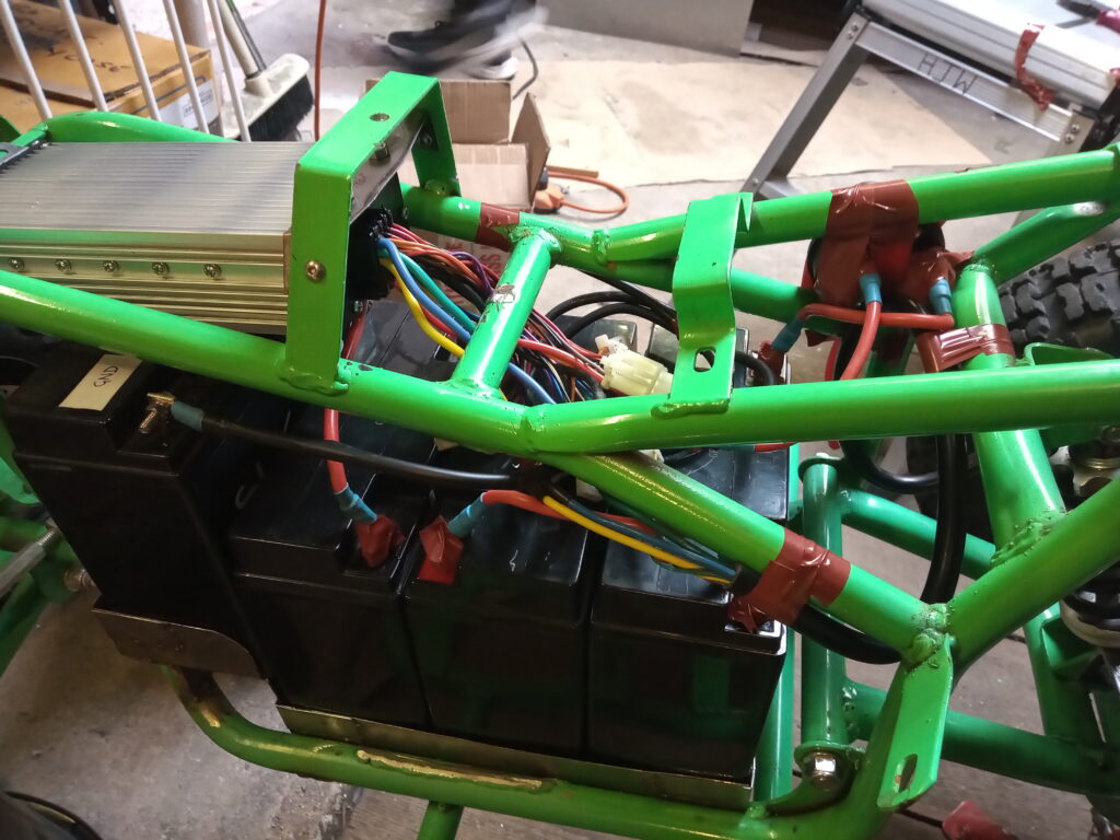
The motor controller was mounted off the flange of the steering rack mount and in between the seat bracket.
All of the wiring is kept mainly hidden in the void between the batteries and under the seat.
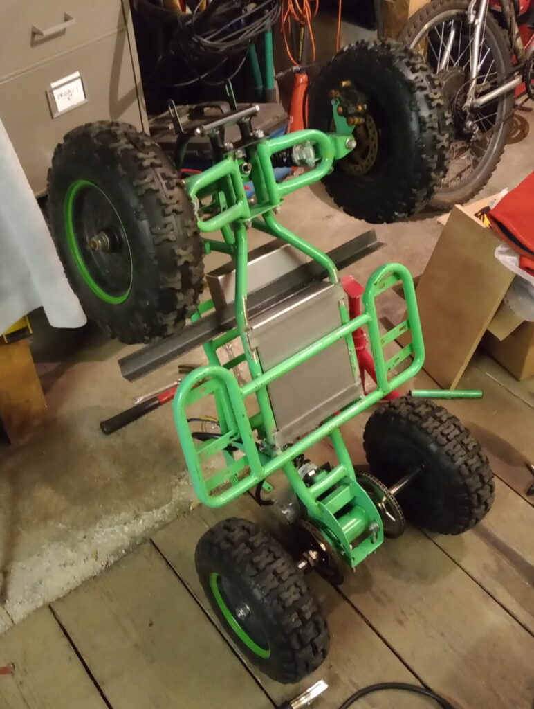
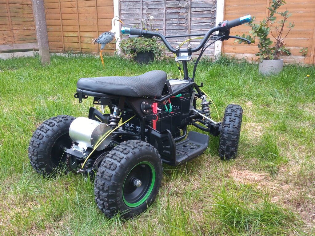
Test Ride 2: Electric Boogaloo
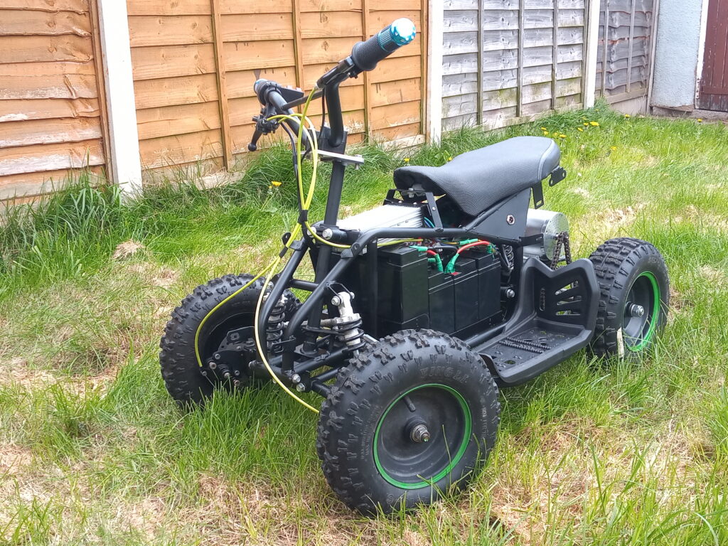
Once the electrics were fitted, it was just a case of pumping up the tyres and taking it out for test ride 2!
The heavy batteries keep the front end a lot more planted to the floor but there is still a tendency to pop a wheelie when leaving from a stationary position.
Aside from only one bolt falling out, the test was generally successful. The chain came loose after each test (you can see the chain slack in the photo below).
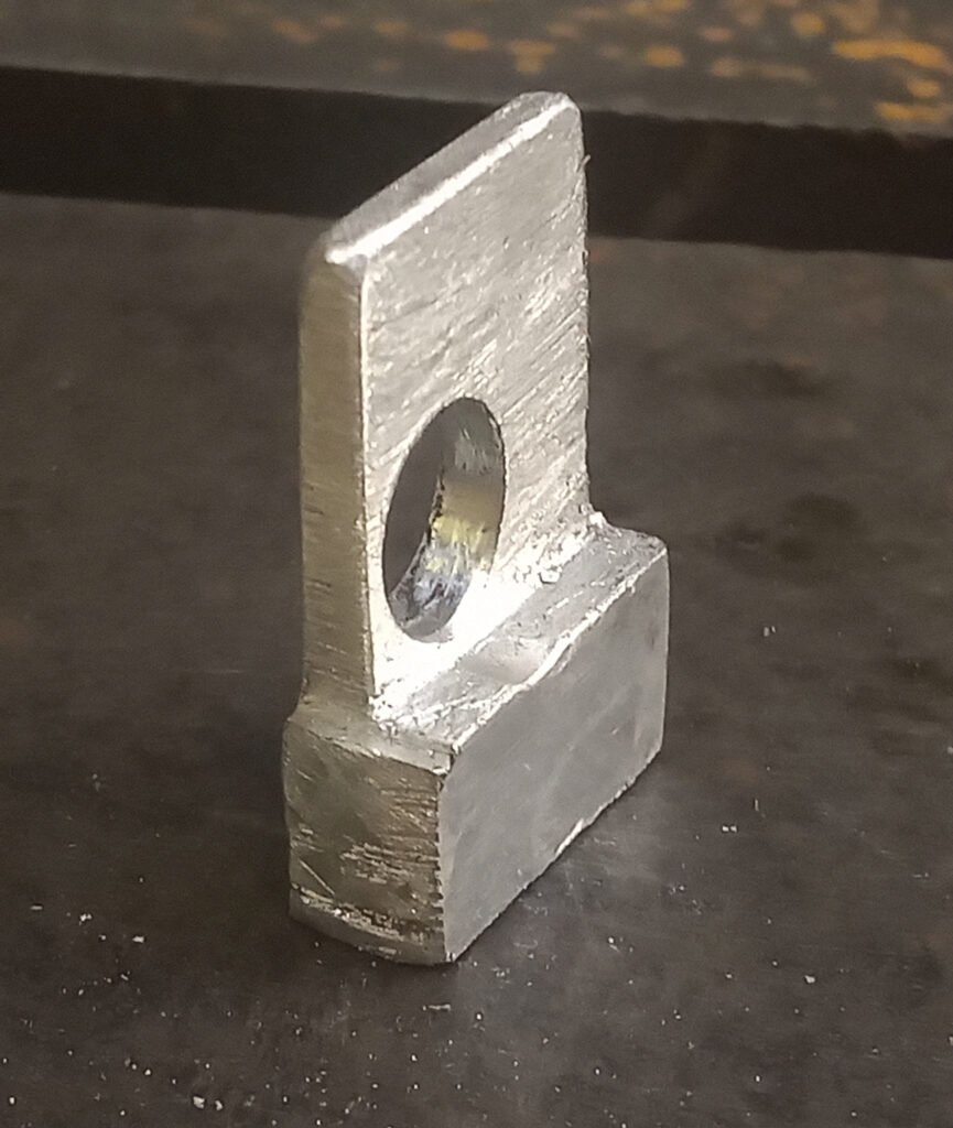
To prevent this from happening a “squat stop” was fabricated from aluminium to prevent the torque from compressing the subframe.

Controls
The accelerator is a standard right hand twist grip. There is a rocker switch for forward and reverse gears, as well as another rocker switch for the 3-speed selector; due to the switch configuration the II & III are swapped.
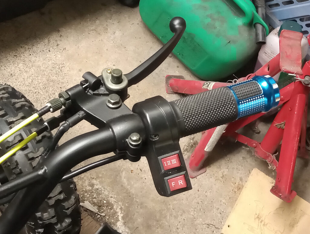
Big red isolator key disconnects the battery from the rest of the system. It’s crude and also not very safe as the car has to be ‘live’ while charging. Therefore, an accidental knock of the accelerator could cause havoc. Thankfully, this can be mitigated by applying the ‘handbrake’ on the front brake lever before charginging.
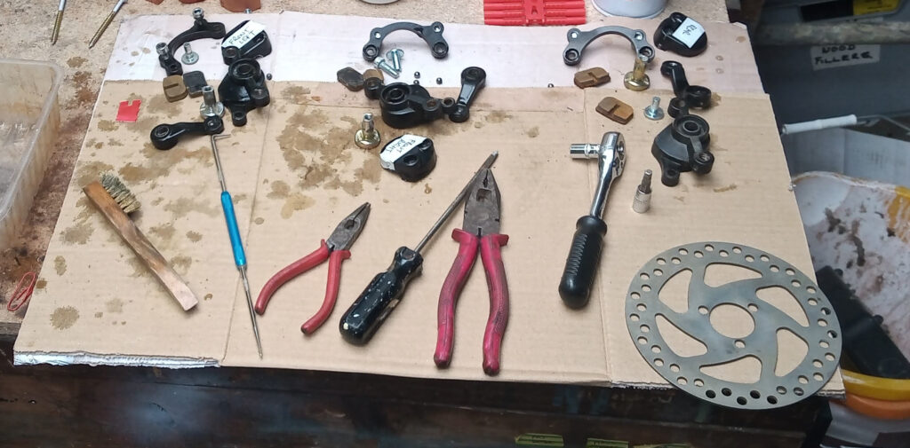
Brakes
On the subject of brakes. The existing callipers were thoroughly refurbished and fitted with new brake pads. The discs were also refurbished.
The right-hand brake lever does the two front brakes and the left-hand brake lever does the rear brake. Pulling either brake lever cuts power to the motor; so no donuts, sadly.
Final Finishes
A full deconstruction was needed to paint the quad. There is something really disheartening about taking apart something you’ve spent so long putting together.
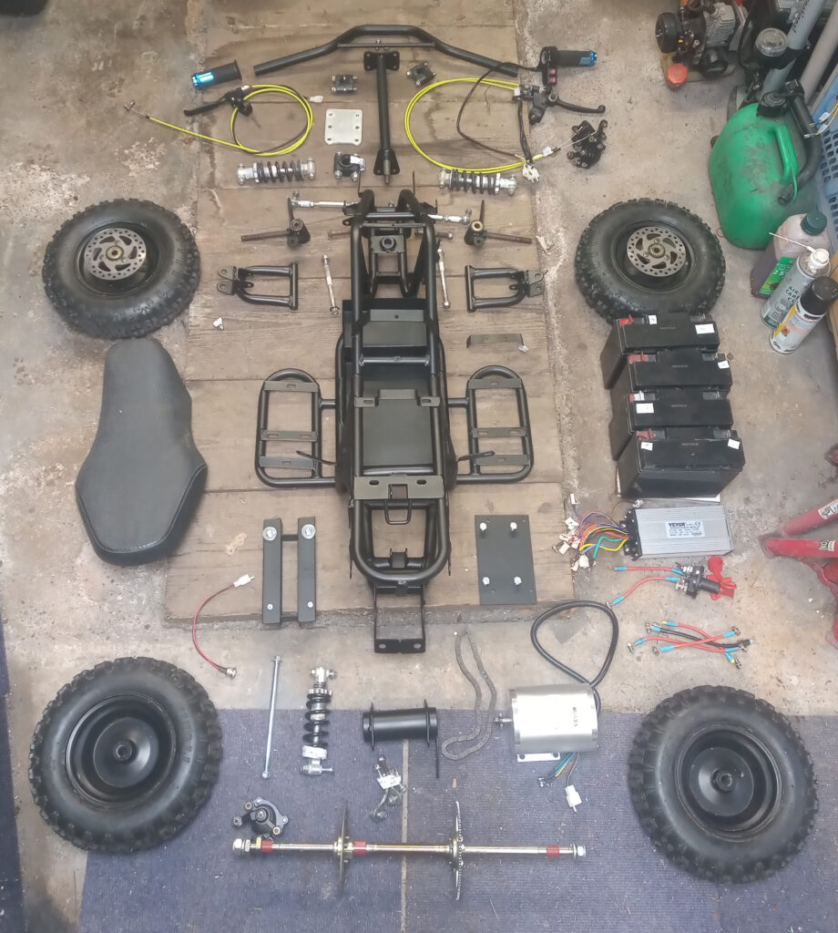
Once all of the components have been painted, you are left with a ‘flat-pack’ quad to assemble. Simple!
Future Plans
There were grand plans of using an Arduino to measure a bunch of sensors and display the info on a circular display screen. I even purchased the 48V to 5V buck converter and even made prototype speedomoter. The speed controller also has connectors for various lights , as well as a proper ‘ignition’ key switch.
With some minor modifications (namely adding a fuse (already purchased) & securing the batteries), this quad could be entered in to a Hacky Racers event, but space and time are two luxuries I don’t have, so the quad was sold on eBay to live a new life with a fresh owner.
Last updated: 22/11/2024
Previously edited: 27/09/2022