Born from a thirst for data and a DHT11 temperature and humidity sensor came the Arduino based weather station.
At the time of writing (23/08/2022), the external transmitter has been sending data for the past eight days. There are also two internal base stations; the first is based around an Arduino Uno, the second is based around an ESP32.
External Transmitter
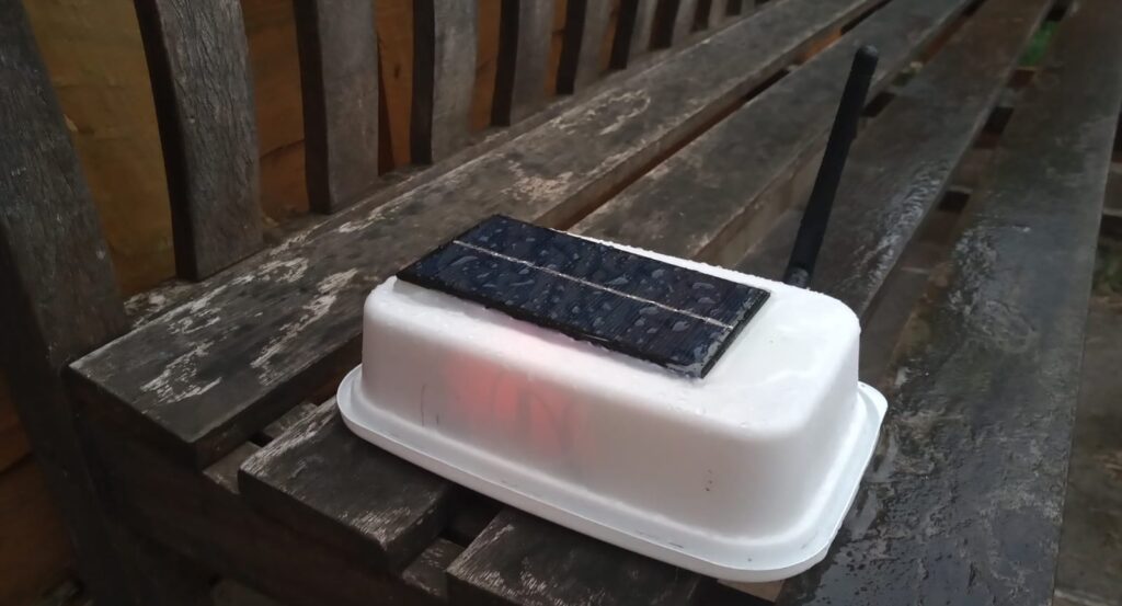
The external transmitter is powered by a 10,000mAh Li-Po cell connected to a 1W solar panel via a CN3065 control board.
Power consumption is kept to a minimum by using the LowPower.h library to place it in a deep sleep, only awaking once every 8 seconds to take a sensor reading and send it.
The sensors fitted are currently:
- BME280 for temperature, humidity and pressure.
- BH1750 for light intensity.
The case is made from a spare plastic container from a Chinese take-away and spray painted white.
Internal Base Station
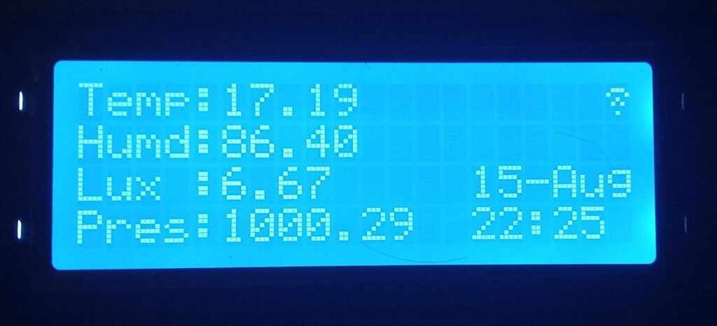
The base station is fitted with a 20×4 I2C LCD display, currently showing the external temperature, humidity, light intensity and barometric pressure.
The display also shows the date and time of the last recorded transmission along with the connectivity status in the top right hand corner.
Every transmission received is saved to a file on a SD card for later processing. At present, there will be approximately 10,000 transmissions a day.
The datalogging shield also has a DS1307 RTC module that handles the date & time requirements.
Wireless connection between the external transmitter and internal receiver is achieved with a pair of nRF24L01+PA+LNA modules with duck antennas. (The ESP32 is using a standard nRF24L01 module to receive the data on the same channel).
The initial test was set up to check the long-term battery life of the transmitter and the general reliability and connectivity of the system in a ‘real-world’ situation.
Results From Test

Over the course of 22 days, 21hrs, 14min & 12 seconds, a total number of 183,275 transmissions were successfully received – approximately once every 10.8 seconds.
These transmissions contained data for the temperature, humidity, atmospheric pressure and light intensity measured from a remote location in the back garden.
In total, 733,100 individual measurements were recorded to the SD memory card.
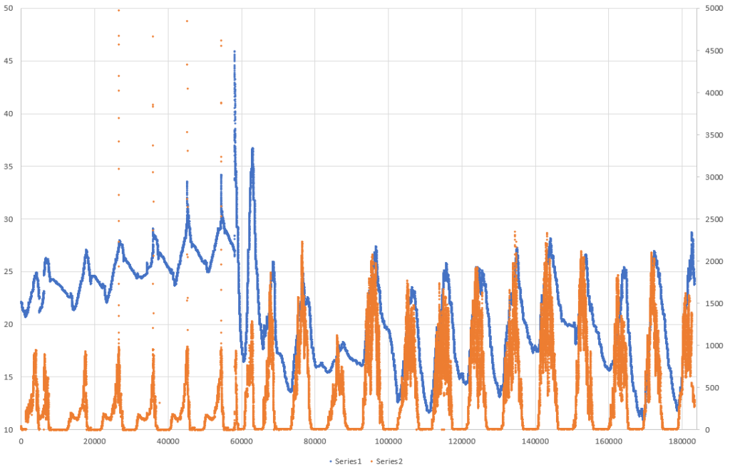
Series 2 = Light intensity in lux (to provide detail, the y-axis has been cropped from a max of 25,000 lux)
As there was no data collected on the effects of any solar charging it’s impossible to determine the exact power usage. Dividing the total size of the battery cell (10,000mAh) by the number of hours in operation (549 hours) returns a mean average of 18mA.
Sadly, this battery life was below expectations as I had hoped for at least 30 days continuous usage as a minimum.
Hopefully with some relatively simple modifications to the hardware and software, the drain on the battery can be reduced.
In addition to this, the transmitter was kept in the shade to prevent overheating as the sensor was recording temperatures nearing 60 degrees in the full sunlight.
Future Plans
External Transmitter
On the list of things to do with the external sensor are:
- Create a proper enclosure for the electronics and sensors.
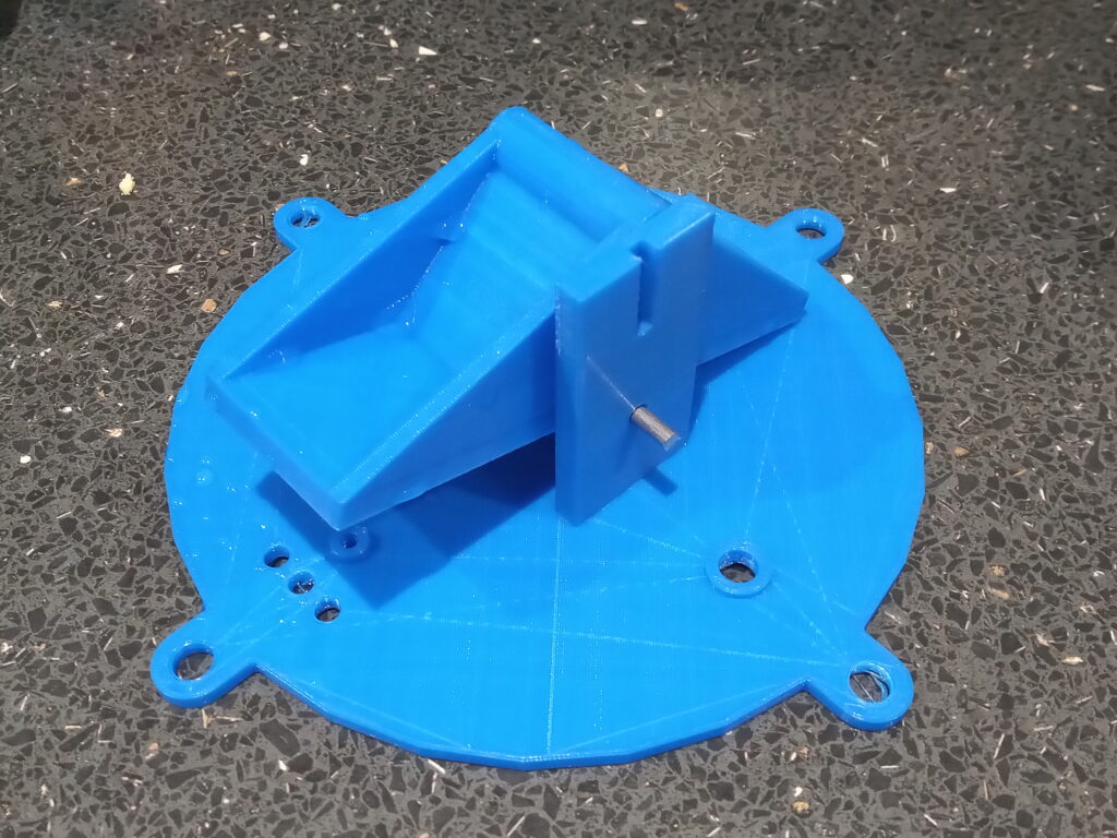
- Add a rain gauge (currently at working-proof-of-concept stage)
- Add wind speed sensors
- Add wind direction sensors.
- Have a battery level sensor.
Also general fettling of the wiring and wireless to improve connectivity and range.
Internal Base Station
Adding features also adds size to the sketch and the Arduino Uno was becoming unstable. Therefore development of a new base station is underway with an ESP32.
The display has been upgraded to a 1.3inch colour TFT ST7789 screen .
After many hours troubleshooting the SPI connections and pin definitions I was able to use the VSPI bus for the nRF24L01 radio and the HSPI bus for the display.
The next step is to integrate an SD card module for data logging. The SD card also uses the SPI interface which I’m sure will be a nice head scratcher.
One of the reasons for purchasing this domain was the hope to be able to host the weather data online. I’m under no illusion that this is will be tracy difficult; the ESP32 does have wifi capabilities. One step at a time.
Media Dump
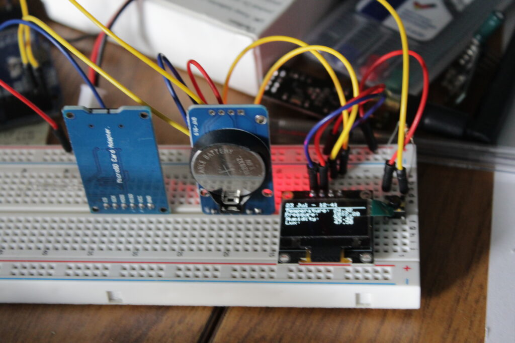
Temp prototype using 0.96 inch OLED display and more accurate DS3231 real time clock.
The Adafruit GFX library took up a lot of memory.
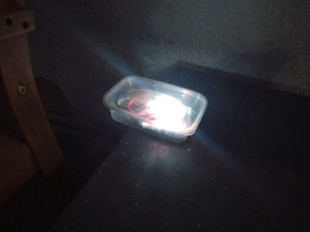
The original sensor unit was powered by a USB power bank. The power bank had a auto-shut off, so a bright LED was added to draw enough current to keep it running.
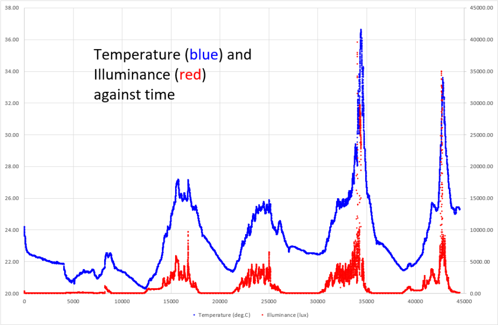
Graph showing the correlation of temperature with illuminance. In layman’s terms: the sensor heats up when it’s in the sun.
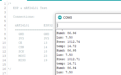
One of the early read outs after establishing the nRF24L01 connection on the ESP32.
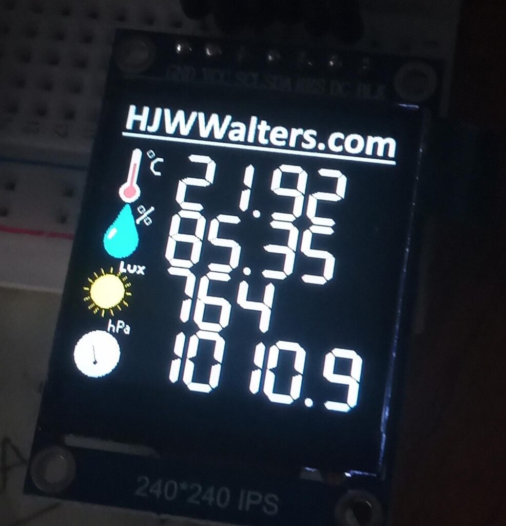
All of the symbols were created on MS Paint
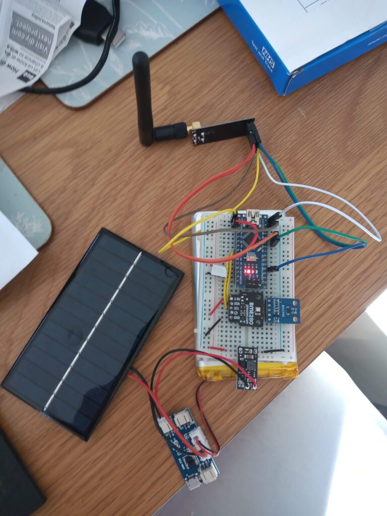
The innards of the external transmitter.
Last updated: 29/09/2022