The SD library takes up a significant amount of memory on the Arduino Uno (328P) and leaves very little for the remainder of your project. This is a hacky get-around for using a data logging shield with an Arduino Mega to unlock that sweet 256kB of flash storage.
Gather the Resources
This is the list of things you’ll need to complete your own electrical butchery:
- Arduino Mega 2560 (obviously)
- Data logging shield (I’ve used the V1.0 from ‘deek-robot’. Adafruit do a better version which probably doesn’t have half the problems).
- Female pin headers; six in total to connect the ICSP pins.
- Hook up wire.
- A suitable memory card (I’m using a 4GB micro SD in an adapter).
- CR1220 button battery for the RTC.
- A soldering iron, flux, solder and other soldering products.
- Patience. Lots of patience.
Hook Up & Hack It
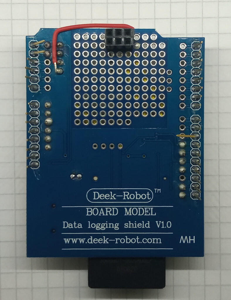
First off; solder the female pin headers to the underside of the shield where the ICSP socket is. This will handle the SPI communications for the SD card. The above picture gives a good indication of what I’m wittering about.
The top side of the board is pictured below.
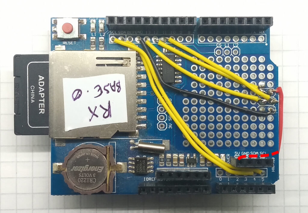
For some strange reason, the SDA and SCL at the top left aren’t actually connected to anything, so you’ll need to solder these back to pins A4 and A5 respectively. This is probably where the Adafruit shield is better.
The SPI pins of the ICSP pins need to be wired accordingly. Looking at the above image for reference the connections should be made as such:
- Top left ICSP > D12 (MISO)
- Top right ICSP > 5V
- Middle left ICSP > D13 (SCK)
- Middle right ICSP > D11 (MOSI)
- Bottom left ICSP (not connected)
- Bottom right ICSP > GND
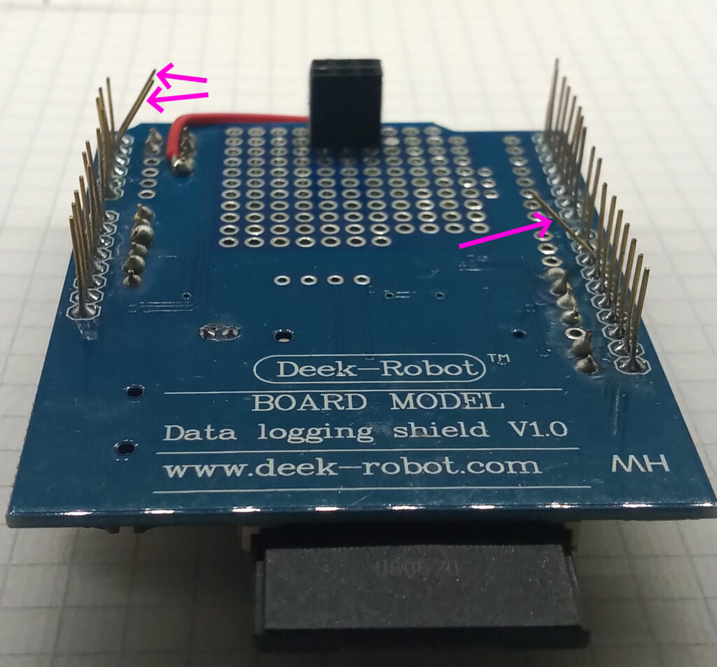
The final part is to then ‘disable’ the original I2C (A4 & A5) and chip select (D10) pins of the shield. I’ve done this by bending them out a bit as highlighted by the pink arrows in the photo below.
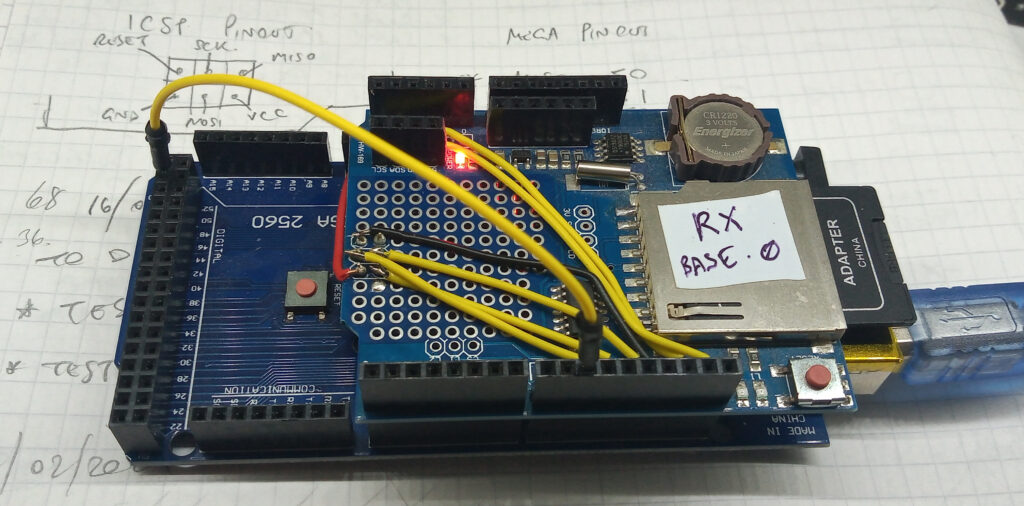
To complete this abomination; a bit of hook-up wire is needed to reassign the chip select pin. So, connect D10 of the shield to D53 of the Mega 2560 – this is evident in the topmost photo.
For some reason, declaring the chip select pin as D10 in the software didn’t seem to work. I don’t know why, and to be honest, I’m not that bothered.
Results
The proof of the pudding is in the eating, as the proof of the hack is in the serial monitor. So here are a couple of screen shots from the serial monitor using the example sketches from the RTC and SD libraries.
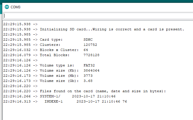
Proof of the SD card working.
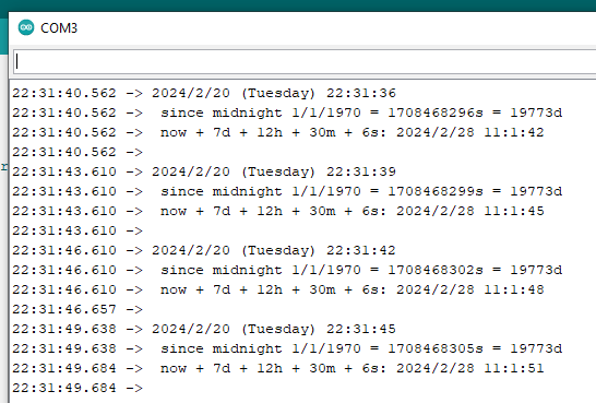
Proof of the RTC working.
To be honest; the only reason why I’ve done this is because the standard cheap SD card modules use a shit logic-level converter which buggers up the SPI bus for any other devices (namely nRF24L01 transceivers). I believe the Adafruit SD card modules don’t suffer from this problem, but I’ve not tested.
Best of luck!
Page created: 24/02/2024