Need to measure DC current in a circuit? The ACS712 an inexpensive hall effect current sensor that can measure up to 30 Amps!
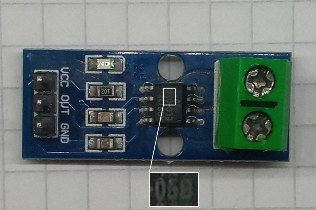
There are three versions available: 5A, 20A and 30A. These are “easily” identifiable from the markings on the chip with the 5 amp version ending in -05B, the 20 amp version ending in -20A, and the 30 amp ending in -30A.
This is a short write-up on how to use the -05B version with an Arduino Nano.
Hardware
There are two circuits involved: the circuit taking the measurements and the circuit being measured.
For the former; the connections are:
- VCC > 5V on the Arduino (or 3.3V if your MCU is 3.3V)
- GND > GND on the Arduino
- OUT > A0 on the Arduino (Or any analogue input pin)
For the device on test; break the circuit where you want to take the measurement. Insert one end of the break in to one screw terminal and the other break into the other screw terminal. Alternatively; use an additional wire rather than breaking the circuit.
Software
In order for this current sensor to give you any meaningful reading, you need to test it against a known benchmark.
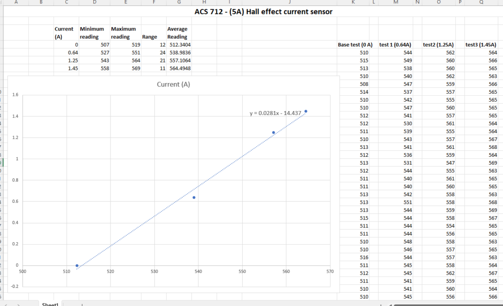
Using the code to the right; record a series of values from the analogue input pin over aa series of known currents.
Once you have this data, you can pump it in to Excel, create a scatter graph, insert a linear trendline and enable the equation to get your conversion values.
const int sensorPin = A0;

void setup() {
  Serial.begin(9600);
}

void loop() {
  int a = analogRead(sensorPin);
  Serial.println(a);
  delay(100);
}
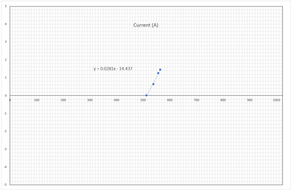
It’s worth noting that this test range is small. The graph to the right shows the full range of possible values.
This is is further compacted by the fact that the sensor also does reverse currents; so half the analogue range is out of use if you’re using DC.
Now armed with our calculated values for the rate and intercept, we can whack it back in to some code to get a meaningful output. This is the code I used:
// ACS712 Current Sensor - 5A version (-05B)
//Pin declarations
const int sensorPin = A0;
//Insert your two calculated values here
const float multiplier = 0.0281; //obtained from testing
const float intercept = -14.437; //obtained from testing
void setup() {
Serial.begin(9600);
}
void loop() {
int a = analogRead(sensorPin);
float current = (multiplier * a + intercept);
Serial.print("The current is: ");
Serial.print(current);
Serial.println(" Amps");
delay(100);
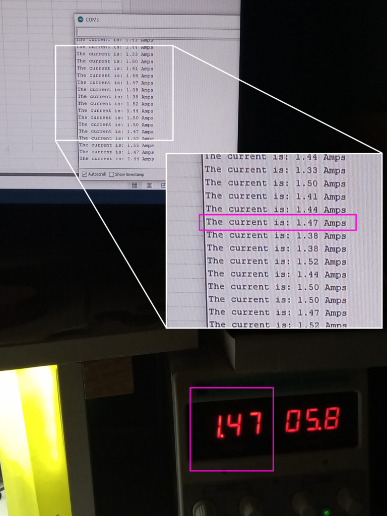
}And this was the result I achieved…
Conclusion
If you want a module that will give you a lovely digital output then look elsewhere. If you want a module that will give you precision then look elsewhere. If you want a module that works straight out of the box with no calibration then look elsewhere. This will not give you any of that.
If, however, you don’t want to spend mega bucks on a sensor then this module is perfect. If you only want to use a single pin on your microcontroller then this module is perfect, and if you want to be able to measure relatively high currents and can already measure high currents then this really is the perfect module for you.
Side note: I also have the 30 Amp version which was going to be used with the quad project to give a power dial. However, I don’t have any reliable means to calibrate the module accurately.
Page created: 04/06/2024