Does your beloved dog like to communicate with other dogs that pass by your window? Is their method of communication loud? Do you want to put a stop this?
If the answer to all of those questions is ‘yes’, then what you need is the Bark Activated Roller Bind.
This clever device listens out for any loud ‘woofs’ and lowers the blind to distract your beloved canine from whatever was upsetting it.
There are no other sensors or wires required: this device simply pushes on to the roller blind in place of the existing pull cord fixing.
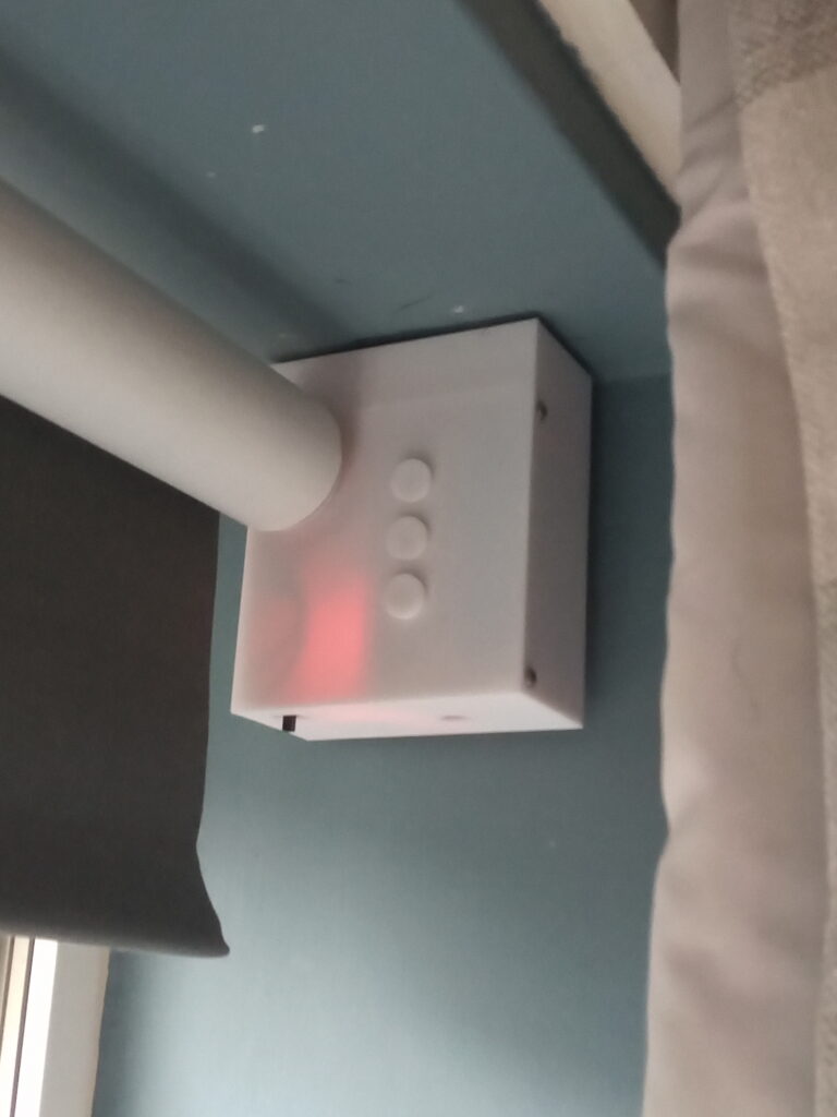
How it Works
The operation is simple; the brains of the contraption are on an Arduino Nano that uses an electret microphone paired with an LM393 comparator forms the ‘ears’ which detect any loud noises.
Motion is brought to the blind by using a geared DC hobby motor driven by an L293d driver. The motor also has a AS5600 rotatory encoder on the reverse side to provide positional information.
The front control panel is a custom array of switches and 1.8mm LEDs. The design can be seen in more detail here.
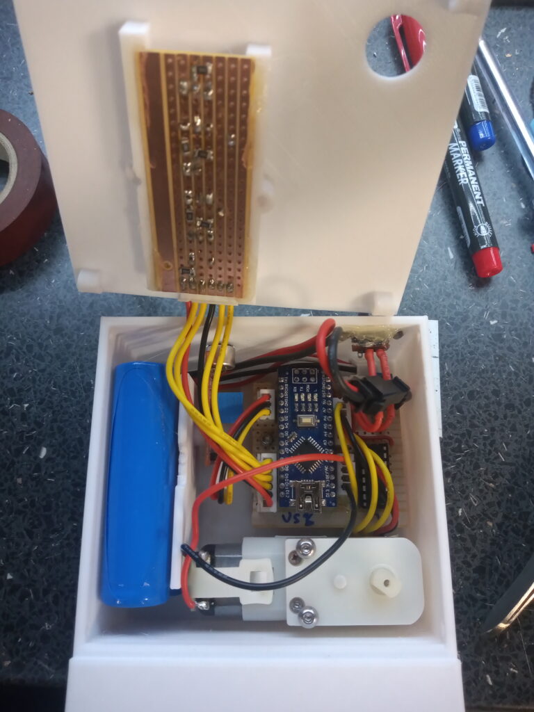
Behind the Scenes
To find your way through a maze, it’s doubtless you’ll encounter some dead-ends.
Here are some photos of the various stages it took to get here.
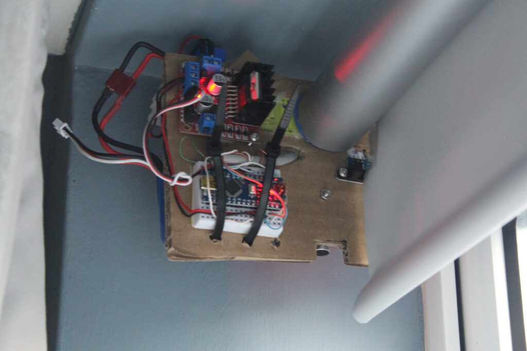
This is the first prototype using an L298n driver and IR gate to detect the blind position.
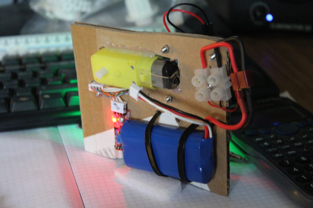
The reverse of the carboard prototype looks like an improvised explosive device.
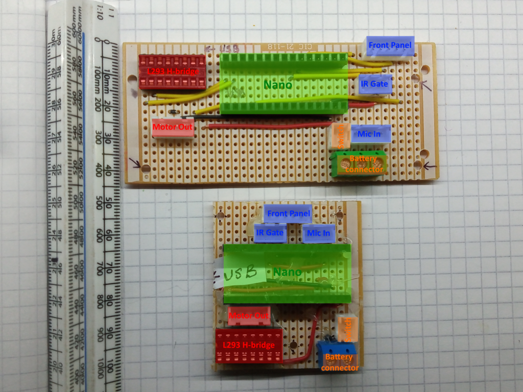
You can see the evolution of the circuit – the irony is that neither of these made it to the final product.
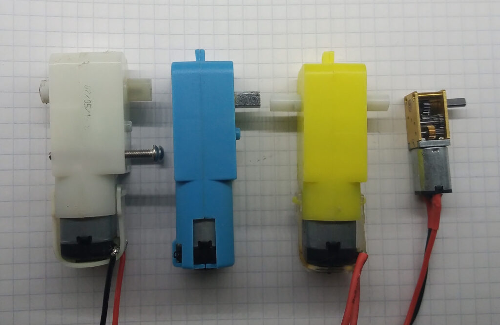
The selection of motors used; the white case on the left was the final choice as it had an integral clutch. But this does limit the physical weight of the blind.
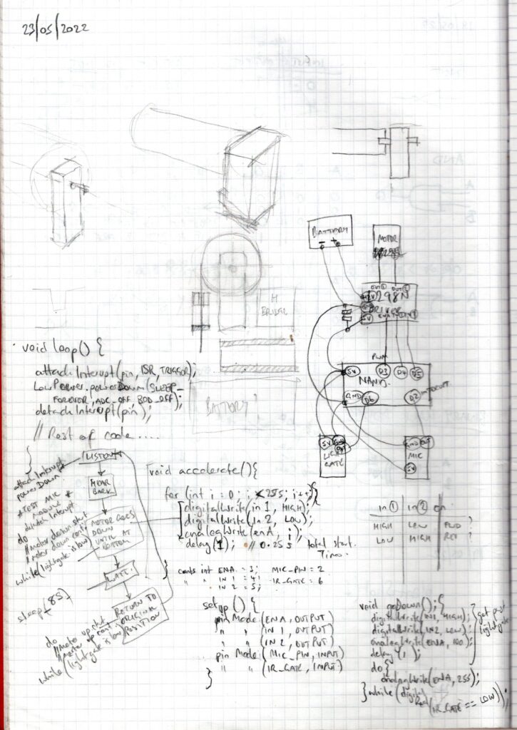
This was the original scribbles for the program flow and wiring layout.
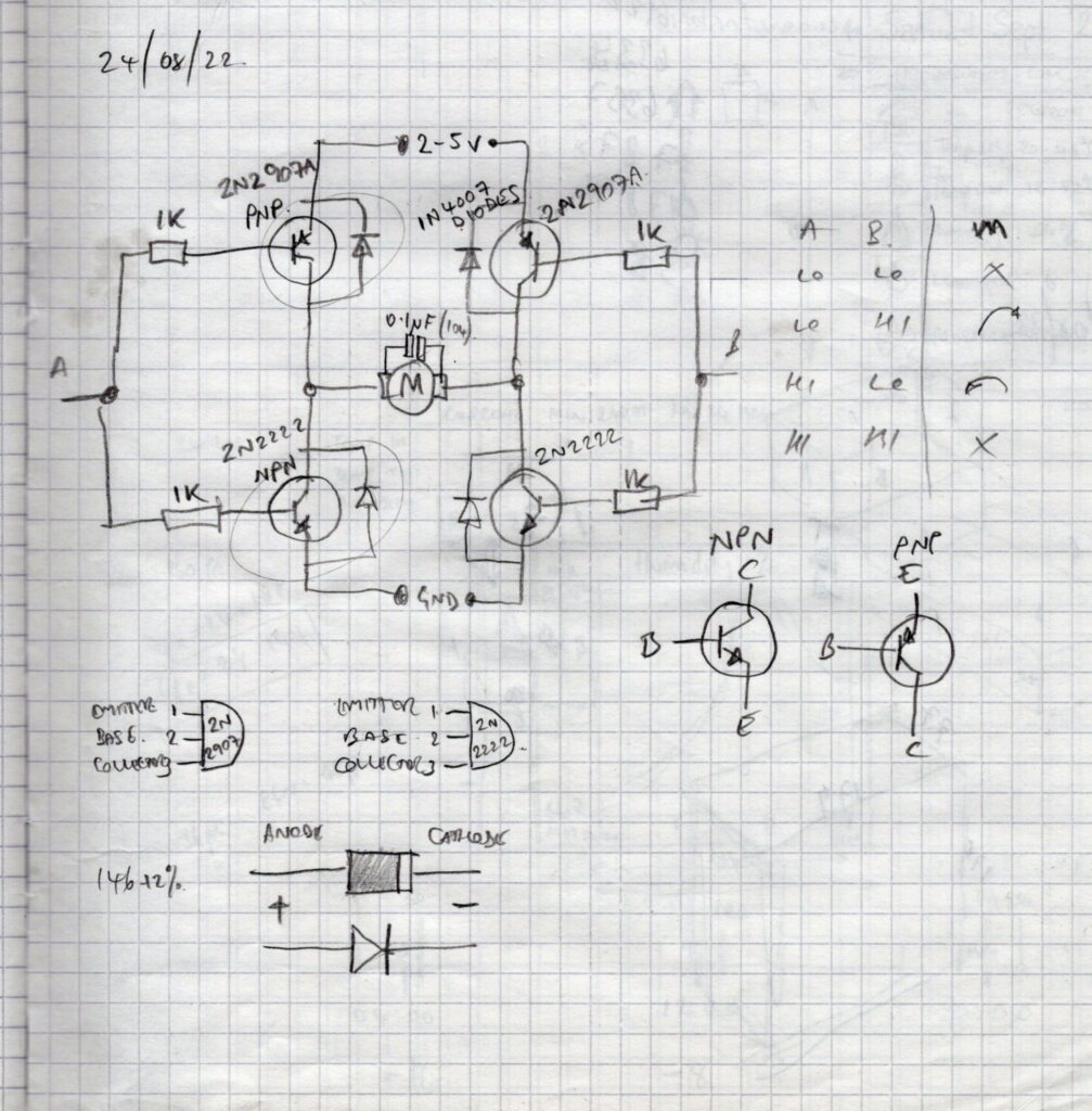
Before realising the L293d was a thing, I attempted to build a H-bridge to control the motor with discrete components.
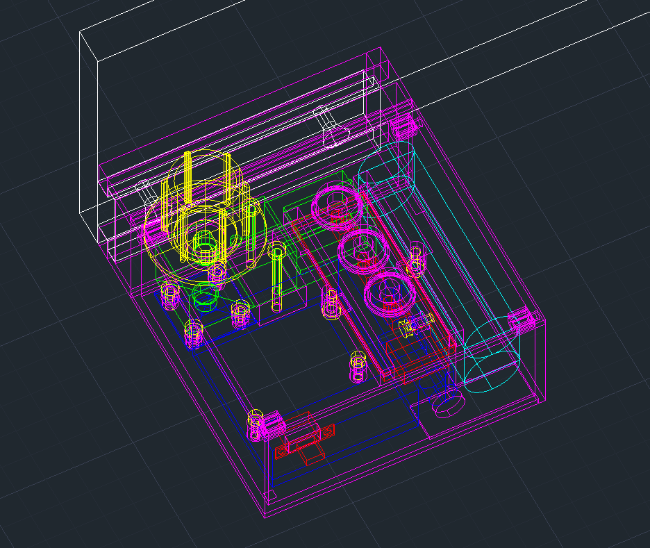
The whole thing was designed with 6 year old architectural design software.
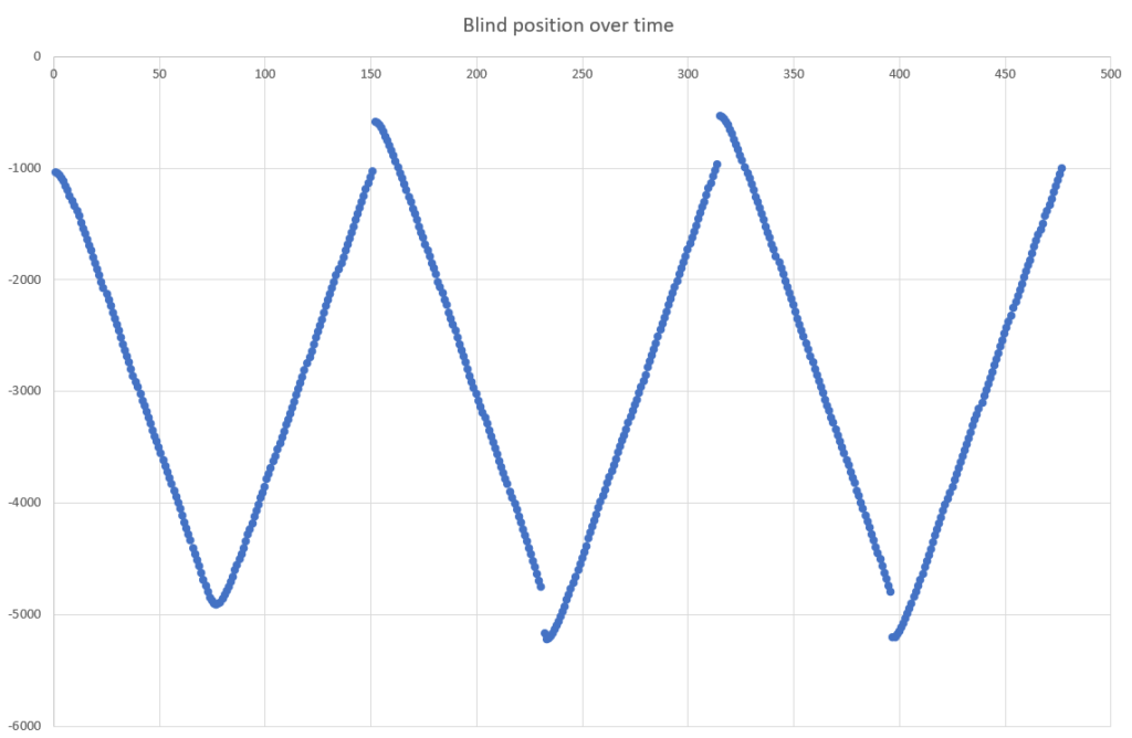
During the debugging phase, it became necessary to output the blind position over time. The first ‘V’ is the test run. The gaps between the other \ and / are a result of rotational inertia pulling the blind after the motor has stopped.
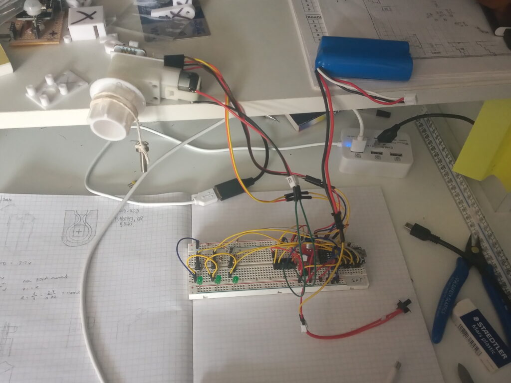
Bench testing the control system of the motor and magnetic encoder.
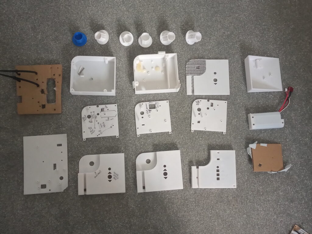
The use of white filament allows for easily marking revision notes on the actual model.
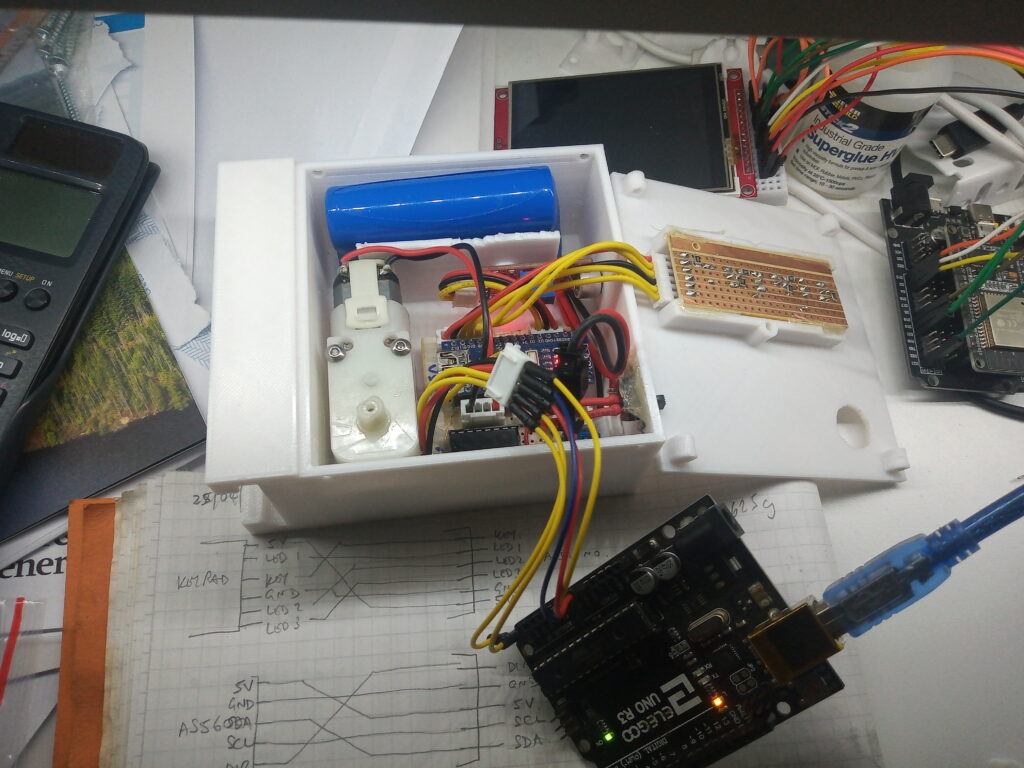
Bug hunting by using a second Arduino to test the hardware. After several hours of head scratching it turns out the keypad was upside-down!

Literal blood went in to this project as I sliced my thumb with a Stanley knife while whittling my poorly designed case
Future Plans
At the moment, the contraption works. However, as the window is over two metres wide, the motor is audibly straining when retracting the blind and the integral clutch is at full limit.
Quite simply, a stronger motor is needed. For this a new driver would be required and most likely a larger power source, too. This would be effectively starting over again.
At the same time, it would be good to have a remote to control the blind, maybe a solar panel, too. Whom knows!
Honestly, after spending two years designing, redesigning, revising and refitting various parts, the chance that the next version will happen is slim. Maybe check back in another two years time…
Page created: 04/07/2022
Last updated: 28/07/2024