This page will show you how to show a real time image from the ESP32-CAM to the 128×64 pixel LCD with the ST7920 driver.
The big problem with this is converting an 8-bit value (256 greyscale) to a 1-bit value (monochrome). The code below does this by using a simple mid-point threshold, so if a pixel is above the mid-value of 127, the display draws a pixel on the screen.
While the display is 128×64 pixels, the output is actually 120×64 pixels due to pixel binning on a 240pixel camera frame giving a max width of 120 pixels.
Hardware
This requires three main components: the ESP32-CAM, ST7920 display, and an FTDI adapter for programming and serial communications with the computer. There are a couple of passive components, too: a 220ohm resistor for the backlight, and a 330uF capacitor on the 5V power rail.
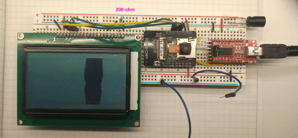
The circuit connections between the display and the ESP32-CAM are as per the table below:
| Pin number | Pin name | Connection |
|---|---|---|
| 1 | Ground | Common ground |
| 2 | VCC | Will depend on display type. The above uses 5V. |
| 3 | V0 | Not connected |
| 4 | RS | ESP32-CAM GPIO 15 (This can be changed in software) |
| 5 | R/W | ESP32-CAM GPIO 13 (This can be changed in software) |
| 6 | E | ESP32-CAM GPIO 14 (This can be changed in software) |
| 7 | DB0 | Not connected |
| 8 | DB1 | Not connected |
| 9 | DB2 | Not connected |
| 10 | DB3 | Not connected |
| 11 | DB4 | Not connected |
| 12 | DB5 | Not connected |
| 13 | DB6 | Not connected |
| 14 | DB7 | Not connected |
| 15 | PSB | Common Ground |
| 16 | (NC) | Not connected |
| 17 | RST | Not connected |
| 18 | VOUT | Not connected |
| 19 | BLA | 5V via a 220ohm resistor. OR, directly to a 3.3V feed |
| 20 | BLK | Common Ground |
This write-up makes the assumption that you know how to programme the ESP32-CAM already.
Software
The below sketch currently achieves a frame rate of 8.3 FPS. Interesting, the time seems to alternate from 106ms per frame to 134ms per frame, so really the frame rate is between 9.4 – 7.5 FPS. There will likely be inefficiencies.
#include <Arduino.h>
#include <U8g2lib.h>
#include "esp_camera.h"

#define CAMERA_MODEL_AI_THINKER
#define PWDN_GPIO_NUM     32
#define RESET_GPIO_NUM    -1
#define XCLK_GPIO_NUM      0
#define SIOD_GPIO_NUM     26
#define SIOC_GPIO_NUM     27
#define Y9_GPIO_NUM       35
#define Y8_GPIO_NUM       34
#define Y7_GPIO_NUM       39
#define Y6_GPIO_NUM       36
#define Y5_GPIO_NUM       21
#define Y4_GPIO_NUM       19
#define Y3_GPIO_NUM       18
#define Y2_GPIO_NUM        5
#define VSYNC_GPIO_NUM    25
#define HREF_GPIO_NUM     23
#define PCLK_GPIO_NUM     22

const int clockPin = 14;
const int dataPin = 13;
const int csPin = 15;
uint8_t thresholdValue = 128; //set threshold range 0 - 255

U8G2_ST7920_128X64_F_SW_SPI u8g2(U8G2_R2, clockPin, dataPin, csPin, U8X8_PIN_NONE );

camera_config_t config;
Libraries, Pin Definitions, Constructors and Global Variables.
This uses the U8g2 library for the display, and the standard “esp_camera.h” library.
The pin definitions are based on the AI-Thinker camera board with the OV2640 camera module.
The display uses software SPI on the SD card pins, therefore, you cannot use the SD card at the same time.
void setup() {
  config.ledc_channel = LEDC_CHANNEL_0;
  config.ledc_timer = LEDC_TIMER_0;
  config.pin_d0 = Y2_GPIO_NUM;
  config.pin_d1 = Y3_GPIO_NUM;
  config.pin_d2 = Y4_GPIO_NUM;
  config.pin_d3 = Y5_GPIO_NUM;
  config.pin_d4 = Y6_GPIO_NUM;
  config.pin_d5 = Y7_GPIO_NUM;
  config.pin_d6 = Y8_GPIO_NUM;
  config.pin_d7 = Y9_GPIO_NUM;
  config.pin_xclk = XCLK_GPIO_NUM;
  config.pin_pclk = PCLK_GPIO_NUM;
  config.pin_vsync = VSYNC_GPIO_NUM;
  config.pin_href = HREF_GPIO_NUM;
  config.pin_sscb_sda = SIOD_GPIO_NUM;
  config.pin_sscb_scl = SIOC_GPIO_NUM;
  config.pin_pwdn = PWDN_GPIO_NUM;
  config.pin_reset = RESET_GPIO_NUM;
  config.xclk_freq_hz = 20000000;
  config.frame_size = FRAMESIZE_240X240;
  config.pixel_format = PIXFORMAT_GRAYSCALE;
  config.grab_mode = CAMERA_GRAB_LATEST;
  config.fb_location = CAMERA_FB_IN_PSRAM;
  config.jpeg_quality = 12;
  config.fb_count = 2;

  esp_err_t err = esp_camera_init(&config);

  sensor_t * s = esp_camera_sensor_get();
  s->set_brightness(s, 0);     // -2 to 2
  s->set_contrast(s, 0);       // -2 to 2
  s->set_saturation(s, 0);     // -2 to 2
  s->set_special_effect(s, 0); // 0 to 6 (0 - No Effect, 1 - Negative, 2 - Grayscale, 3 - Red Tint, 4 - Green Tint, 5 - Blue Tint, 6 - Sepia)
  s->set_whitebal(s, 1);       // 0 = disable , 1 = enable
  s->set_awb_gain(s, 1);       // 0 = disable , 1 = enable
  s->set_wb_mode(s, 0);        // 0 to 4 - if awb_gain enabled (0 - Auto, 1 - Sunny, 2 - Cloudy, 3 - Office, 4 - Home)
  s->set_exposure_ctrl(s, 1);  // 0 = disable , 1 = enable
  s->set_aec2(s, 0);           // 0 = disable , 1 = enable
  s->set_ae_level(s, 0);       // -2 to 2
  s->set_aec_value(s, 300);    // 0 to 1200
  s->set_gain_ctrl(s, 1);      // 0 = disable , 1 = enable
  s->set_agc_gain(s, 0);       // 0 to 30
  s->set_gainceiling(s, (gainceiling_t)0);  // 0 to 6
  s->set_bpc(s, 0);            // 0 = disable , 1 = enable
  s->set_wpc(s, 1);            // 0 = disable , 1 = enable
  s->set_raw_gma(s, 1);        // 0 = disable , 1 = enable
  s->set_lenc(s, 1);           // 0 = disable , 1 = enable
  s->set_hmirror(s, 0);        // 0 = disable , 1 = enable
  s->set_vflip(s, 0);          // 0 = disable , 1 = enable
  s->set_dcw(s, 1);            // 0 = disable , 1 = enable
  s->set_colorbar(s, 0);       // 0 = disable , 1 = enable

  u8g2.begin();
  u8g2.setDrawColor(1);
  Serial.begin(115200);
}
Setup ( ) function
The important configuration settings to check on this is the config.frame_size and config.pixel_format.
This setup uses the onboard PSRAM, therefore GPIO 16 is off bounds.
void loop() {

  long startTime = millis();
  u8g2.clearBuffer();
  camera_fb_t  * fb = NULL;
  fb = esp_camera_fb_get();

  for (int y = 0; y < 64; y++) {
    for (int x = 0; x < 120; x++) {
      int framePixel = fb->buf[(((2 * y) + 56) * 240) + (2 * x)];
      if (framePixel > thresholdValue) {
        u8g2.drawPixel(x + 2, y);
      }
    }
  }
  u8g2.sendBuffer();
  esp_camera_fb_return(fb);   //return frame buffer
  long frameTime = millis() - startTime;
  Serial.println(frameTime);
}
The loop ( )
The loop grabs a camera frame, then runs through 64 rows of 120 pixels, checking if the value is greater than 127. If it does then a pixel at that place is drawn.
Simple.
Simply strap GPIO 0, upload the code, remove the strap and restart. Et voila!
Page created: 21/06/2025
Page last updated: 21/06/2025