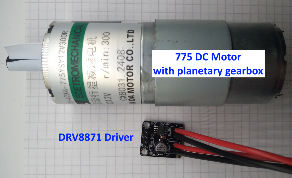
This is a short write-up on how to interface a 775 DC motor with a DRV8871 driver, and use an Arduino Uno to control it.
The DRV8871 is a H-Bridge DC brushed motor driver rated for 3.5 Amp continuous (3.6A peak) [Datasheet here]. The motor used is a 12 V 775 DC motor with a planetary gearbox to reduce the spindle to 300RPM.
For these experiments, I’ll be using a 5 amp bench power supply at to 12.0V. You cannot power this via the Arduino.
Hardware
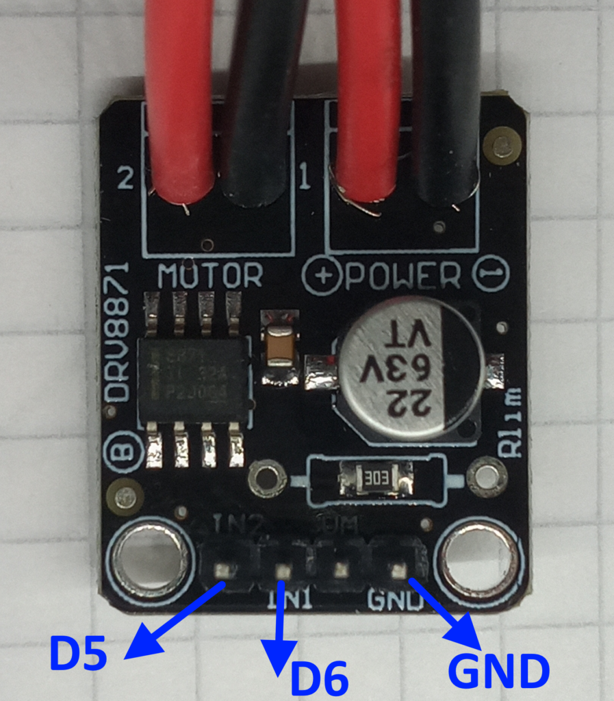
The pinout is simple; the digital side of the driver is connected to the Arduino Uno as such:
- DRV8871 IN1 ==> Arduino Uno D5
- DRV8871 IN2 ==> Arduino Uno D6
- DRV8871 GND ==> Arduino Uno GND
The two larger connectors go to the motor and power supply. I have soldered these as I did not have the correct pitch of screw terminal in stock.
I have also successfully tested this using an ESP32 but with pins 22 & 23 instead.
Software
This driver is like any normal H-bridge which takes two arguments and computes the output as per the truth table below.
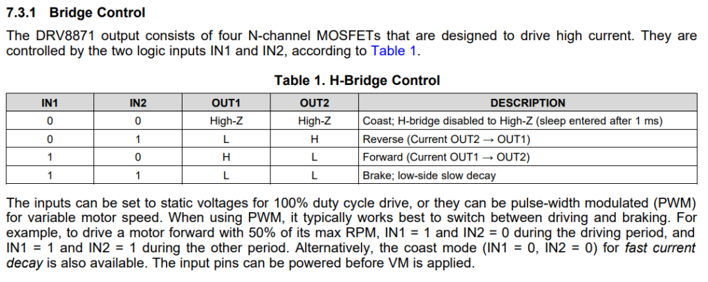
This means that simple digitalWrite( ) and analogWrite( ) functions work plenty well. Below is a sketch which contains simple functions for motion control.
const int IN1 = 5;
const int IN2 = 6;

void setup() {
  Serial.begin(115200);
  pinMode(IN1, OUTPUT);
  pinMode(IN2, OUTPUT);
  digitalWrite(IN1, LOW);
  digitalWrite(IN2, LOW);
  delay(1000);
}

void loop() {
  spinClockwise(2000);
  coast();
  delay(1000);
  spinCounterClockwise(2000);
  brake();
  delay(1000);
}

void spinClockwise(int _duration) {
  Serial.println("Spin motor clockwise");
  digitalWrite(IN1, HIGH);
  digitalWrite(IN2, LOW);
  delay(_duration);
}

void spinCounterClockwise(int _duration) {
  Serial.println("Spin motor counter clockwise");
  digitalWrite(IN1, LOW);
  digitalWrite(IN2, HIGH);
  delay(_duration);
}

void coast() {
  Serial.println("Stop/coast");
  digitalWrite(IN1, LOW);
  digitalWrite(IN2, LOW);
}

void brake() {
  Serial.println("Stop/brake");
  digitalWrite(IN1, HIGH);
  digitalWrite(IN2, HIGH);
}
This sketch drives a motor in one direction for two seconds, before coasting to a stop.
The sketch then reverses the direction of the motor for another two seconds before applying the brake.
If all has gone well then you should see the below.
I experimented with variable speed control and found that the if both inputs start from LOW then the action doesn’t start until about 50%
Whereas reducing from two HIGH signals seems to give a better range of speed controls, but the direction is mirrored as it becomes active low.
I plan to do more experiments using an AS5600 rotary encoder to measure the motion.
Page created: 06/10/2024
Last updated: 06/10/2024