
Catchy title.

Basically, as part of my quest to develop some home-brew computer vision systems, I needed a way to test the algorithms on some real image data. Therefore, I’ve created a method (albeit convoluted) to export a 240×240 pixel greyscale image to Microsoft Excel via the serial monitor.
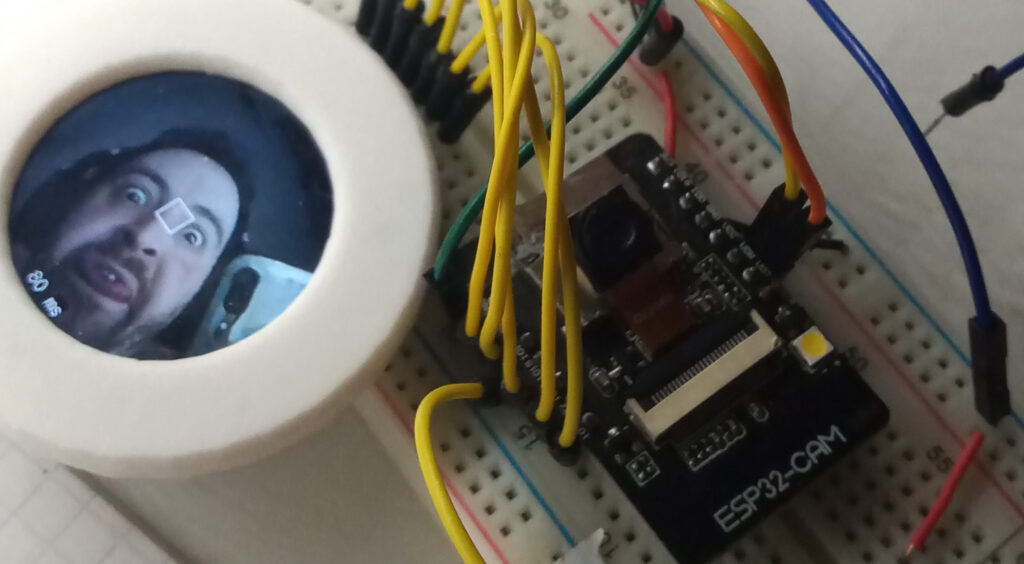
Oh yeah, and it does all of this while displaying the live colour image to a circular TFT display at 12FPS. The disruption to the live image is a single 80ms delay when ‘image capture’ button is pressed.
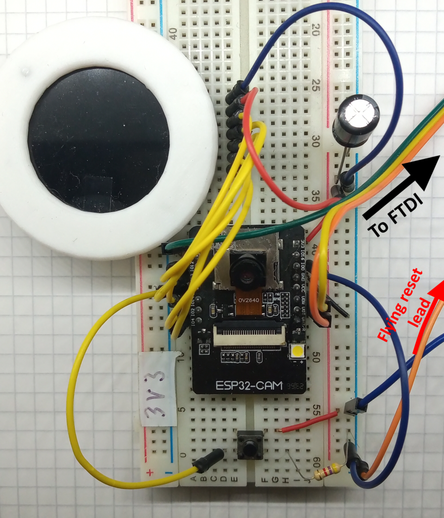
Hardware
The setup for this is the same as used previously. The only exception is the addition of a momentary push button wired to GPIO 15, and pulldown resistor (nominal 4.7-10 kOhm).
Software
Not going to lie. This has taken me weeks to figure out. Not only does it use both CPU cores; but the only way to stop the ESP32 from shitting a brick was to use the onboard PSRAM and the sprintf( ) function.
Refer back to the resource page for the ESP32-CAM and GC9A01 display for the User_Setup.h file. This is needed for the display to work correctly.
There will be better ways to write this code. A lot of the variables still have their “temporary” names (such as a creatively named pointer called *testBuf), and the whole greyscale conversion algorithm is “unique”, to say the least. But none the less, it works.
#include "esp_camera.h"
#include <TFT_eSPI.h> // Hardware-specific library
#include <SPI.h>

#define CAMERA_MODEL_AI_THINKER
#define PWDN_GPIO_NUM     32
#define RESET_GPIO_NUM    -1
#define XCLK_GPIO_NUM      0
#define SIOD_GPIO_NUM     26
#define SIOC_GPIO_NUM     27
#define Y9_GPIO_NUM       35
#define Y8_GPIO_NUM       34
#define Y7_GPIO_NUM       39
#define Y6_GPIO_NUM       36
#define Y5_GPIO_NUM       21
#define Y4_GPIO_NUM       19
#define Y3_GPIO_NUM       18
#define Y2_GPIO_NUM        5
#define VSYNC_GPIO_NUM    25
#define HREF_GPIO_NUM     23
#define PCLK_GPIO_NUM     22

TaskHandle_t Task1;

TFT_eSPI tft = TFT_eSPI();
TFT_eSprite spr = TFT_eSprite(&tft);

camera_config_t config;

uint16_t *scr;
uint16_t *testBuf;

const int buttonPin = 15;
long initalTime = 0;
long frameTime = 0;
long core1refresh = 0;

volatile bool buttonFlag = false;

int n_elements = 57600;
As it says; start by including the libraries, defining the pins, creating some tasks, and initialising the global variables.
void Task1code( void * pvParameters ) {

  tft.init();
  tft.setRotation(0);
  tft.fillScreen(TFT_BLACK);
  tft.setTextColor(TFT_BLACK, TFT_WHITE);
  scr = (uint16_t*)spr.createSprite(240, 240);

  config.ledc_channel = LEDC_CHANNEL_0;
  config.ledc_timer = LEDC_TIMER_0;
  config.pin_d0 = Y2_GPIO_NUM;
  config.pin_d1 = Y3_GPIO_NUM;
  config.pin_d2 = Y4_GPIO_NUM;
  config.pin_d3 = Y5_GPIO_NUM;
  config.pin_d4 = Y6_GPIO_NUM;
  config.pin_d5 = Y7_GPIO_NUM;
  config.pin_d6 = Y8_GPIO_NUM;
  config.pin_d7 = Y9_GPIO_NUM;
  config.pin_xclk = XCLK_GPIO_NUM;
  config.pin_pclk = PCLK_GPIO_NUM;
  config.pin_vsync = VSYNC_GPIO_NUM;
  config.pin_href = HREF_GPIO_NUM;
  config.pin_sscb_sda = SIOD_GPIO_NUM;
  config.pin_sscb_scl = SIOC_GPIO_NUM;
  config.pin_pwdn = PWDN_GPIO_NUM;
  config.pin_reset = RESET_GPIO_NUM;
  config.xclk_freq_hz = 20000000;
  config.frame_size = FRAMESIZE_240X240;
  config.pixel_format = PIXFORMAT_RGB565;
  config.grab_mode = CAMERA_GRAB_LATEST;
  config.fb_location = CAMERA_FB_IN_PSRAM;
  config.jpeg_quality = 12;
  config.fb_count = 2;

  esp_err_t err = esp_camera_init(&config);

  sensor_t * s = esp_camera_sensor_get();
  s->set_brightness(s, 0);     // -2 to 2
  s->set_contrast(s, 0);       // -2 to 2
  s->set_saturation(s, 0);     // -2 to 2
  s->set_special_effect(s, 0); // 0 to 6 (0 - No Effect, 1 - Negative, 2 - Grayscale, 3 - Red Tint, 4 - Green Tint, 5 - Blue Tint, 6 - Sepia)
  s->set_whitebal(s, 1);       // 0 = disable , 1 = enable
  s->set_awb_gain(s, 1);       // 0 = disable , 1 = enable
  s->set_wb_mode(s, 0);        // 0 to 4 - if awb_gain enabled (0 - Auto, 1 - Sunny, 2 - Cloudy, 3 - Office, 4 - Home)
  s->set_exposure_ctrl(s, 1);  // 0 = disable , 1 = enable
  s->set_aec2(s, 0);           // 0 = disable , 1 = enable
  s->set_ae_level(s, 0);       // -2 to 2
  s->set_aec_value(s, 300);    // 0 to 1200
  s->set_gain_ctrl(s, 1);      // 0 = disable , 1 = enable
  s->set_agc_gain(s, 0);       // 0 to 30
  s->set_gainceiling(s, (gainceiling_t)0);  // 0 to 6
  s->set_bpc(s, 0);            // 0 = disable , 1 = enable
  s->set_wpc(s, 1);            // 0 = disable , 1 = enable
  s->set_raw_gma(s, 1);        // 0 = disable , 1 = enable
  s->set_lenc(s, 1);           // 0 = disable , 1 = enable
  s->set_hmirror(s, 0);        // 0 = disable , 1 = enable
  s->set_vflip(s, 0);          // 0 = disable , 1 = enable
  s->set_dcw(s, 1);            // 0 = disable , 1 = enable
  s->set_colorbar(s, 0);       // 0 = disable , 1 = enable

  tft.setTextColor(TFT_WHITE);
  tft.drawString("Loading...", 105, 105, 2);

  for (;;) {
    initalTime = millis();
    //take picture
    camera_fb_t  * fb = NULL;
    fb = esp_camera_fb_get();

    //Transfer camera buffer to screen pointer
    for (size_t i = 0; i < 57600; i++) {    //240x240px = 57600
      //create 16 bit colour from two bytes.
      byte first_byte = fb->buf[i * 2];
      byte second_byte = fb->buf[i * 2 + 1];
      scr[i] = (second_byte << 8) + first_byte;
    }

    spr.drawString(String(frameTime), 100, 220, 2); //print frame time in milliseconds
    spr.drawString("ms", 125, 220, 2);
    spr.pushSprite(0, 0);

    esp_camera_fb_return(fb);   //return the frame buffer back to the driver for reuse

    frameTime = millis() - initalTime;
  }
}
This is the entirety of the code for core_0 that captures the image and displays it on the TFT screen.
Everything above the for( ; ; ) loop is the equivalent to the setup( ) function, but specific to core_0.
Therefore, everything inside the same for( ; ; ) loop is the equivalent to the normal loop( ) function.
void setup() {
  psramInit();

  Serial.begin(500000);

  pinMode(buttonPin, INPUT);

  xTaskCreatePinnedToCore(
    Task1code,   /* Task function. */
    "Task1",     /* name of task. */
    100000,       /* Stack size of task */
    NULL,        /* parameter of the task */
    1,           /* priority of the task */
    &Task1,      /* Task handle to keep track of created task */
    0);          /* pin task to core 0 */

  delay(1000);
}
This is the typical setup( ) function that will run on core_1.
Take note of the baud rate of the serial connection used here (500000 instead of 115200).
void loop() {
  if (digitalRead(buttonPin)) {
    unsigned long core1start = millis();
    buttonFlag = true;
    int *int_array = (int *) ps_malloc(n_elements * sizeof(int));
    int *greyscale_array = (int *) ps_malloc(n_elements * sizeof(int));
    camera_fb_t  * fb = NULL;
    fb = esp_camera_fb_get();

    //Transfer camera buffer to serial buffer pointer
    for (size_t ii = 0; ii < 57600; ii++) {    //240x240px = 57600
      //create 16 bit colour from two bytes.
      byte first_byte_serial = fb->buf[ii * 2];
      byte second_byte_serial = fb->buf[ii * 2 + 1];
      int_array[ii] = (first_byte_serial << 8) + second_byte_serial;

    }
    esp_camera_fb_return(fb);

    //convert to greyscale
    for (int gy = 0; gy < 240; gy++) {
      for (int gx = 0; gx < 240; gx++) {
        greyscale_array[(gy * 240) + (gx)] = convertToGreyscale(int_array[(gy * 240) + (gx)]);
      }
    }

    //serial print data in chunks:  10 x 24px = 1 row, x 240
    for (int s_row = 0; s_row < 240; s_row++) {
      //10 chunks = 1 row
      for (int s_chunk = 0; s_chunk < 10; s_chunk++) {
        //one 'chunk' = 24 pixels
        char serialBuf[145];  //24 sets of 6 char + nul
        sprintf(serialBuf, "%d, %d, %d, %d, %d, %d, %d, %d, %d, %d, %d, %d, %d, %d, %d, %d, %d, %d, %d, %d, %d, %d, %d, %d, ",
                greyscale_array[(s_row * 240) + (s_chunk * 24) + 0],
                greyscale_array[(s_row * 240) + (s_chunk * 24) + 1],
                greyscale_array[(s_row * 240) + (s_chunk * 24) + 2],
                greyscale_array[(s_row * 240) + (s_chunk * 24) + 3],
                greyscale_array[(s_row * 240) + (s_chunk * 24) + 4],
                greyscale_array[(s_row * 240) + (s_chunk * 24) + 5],
                greyscale_array[(s_row * 240) + (s_chunk * 24) + 6],
                greyscale_array[(s_row * 240) + (s_chunk * 24) + 7],
                greyscale_array[(s_row * 240) + (s_chunk * 24) + 8],
                greyscale_array[(s_row * 240) + (s_chunk * 24) + 9],
                greyscale_array[(s_row * 240) + (s_chunk * 24) + 10],
                greyscale_array[(s_row * 240) + (s_chunk * 24) + 11],
                greyscale_array[(s_row * 240) + (s_chunk * 24) + 12],
                greyscale_array[(s_row * 240) + (s_chunk * 24) + 13],
                greyscale_array[(s_row * 240) + (s_chunk * 24) + 14],
                greyscale_array[(s_row * 240) + (s_chunk * 24) + 15],
                greyscale_array[(s_row * 240) + (s_chunk * 24) + 16],
                greyscale_array[(s_row * 240) + (s_chunk * 24) + 17],
                greyscale_array[(s_row * 240) + (s_chunk * 24) + 18],
                greyscale_array[(s_row * 240) + (s_chunk * 24) + 19],
                greyscale_array[(s_row * 240) + (s_chunk * 24) + 20],
                greyscale_array[(s_row * 240) + (s_chunk * 24) + 21],
                greyscale_array[(s_row * 240) + (s_chunk * 24) + 22],
                greyscale_array[(s_row * 240) + (s_chunk * 24) + 23]);
        Serial.print(serialBuf);
      }
      Serial.println("");   //new line
    }

    free(int_array);
    unsigned long core1end = millis();
    core1refresh = core1end - core1start;
    Serial.print("Image process time(ms): ");
    Serial.println(core1refresh);
  }
}
The loop( ) function simply runs an if( ) statement to see if the button pin is high.
Upon reading a high value, the PSRAM memory is allocated for the camera frame data and also the equivalent greyscale data.
After converting to greyscale, the data is outputted to the serial monitor in chunks of 24 pixels.
A total frame is made of 240 rows consisting of 10 chunks of 24 pixels.
Even at baud rates 4 times faster than standard, it still takes about six and a half seconds to transmit the data.
uint16_t convertToGreyscale(int RGB) {

  uint16_t R = (0b1111100000000000 & RGB) >> 11;
  uint16_t G = (0b1111110000000000 & (RGB << 5)) >> 11;
  uint16_t B = (0b1111100000000000 & (RGB << 11)) >> 11;

  uint16_t greyscale = (R * 30 ) + (G * 59) + (B * 11);   //returns theoretical 0-3200
  return greyscale;

}
Finally we come to the greyscale conversion function. This is where liberties have been taken.
Three bit masks are applied to the RGB value to express the component R, G and B values, before being bit shifted to the right to truncate them.
The conversion is based off the YUV to RGB weighted values as defined in BT.470. (wikipedia section here).
To avoid excessive floating point maths, I converted the weightings by rounding the decimal to 2 places and multiplying it by 100. As such, the theoretical maximum value is 3200.
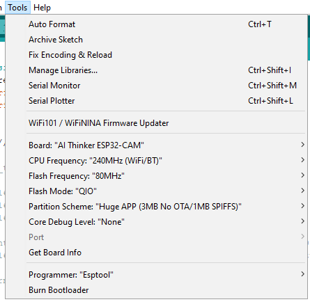
These are the board settings that I used to compile the AI-Thinker ESP32-CAM:
Once done uploading, reset the ESP32-CAM and press the button when you want to capture the image shown on the display. All being well, you should get a stream of data as shown in the video.
The theoretical framerate is 0.15FPS.
And then what?
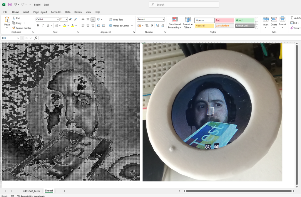
Once the data has dumped into the serial monitor, copy and paste it over to notepad and save the file. From the ‘Data’ tab Excel, click on “From Text / CSV” and select the notepad file you’ve just created. Click load and hear your computer groan as it sorts through 57,600 comma separated values.
Resize the cells so that they’re square, apply some conditional formatting, et voila, you have a greyscale image with each pixel represented by a number from 0-3200.
But then what?
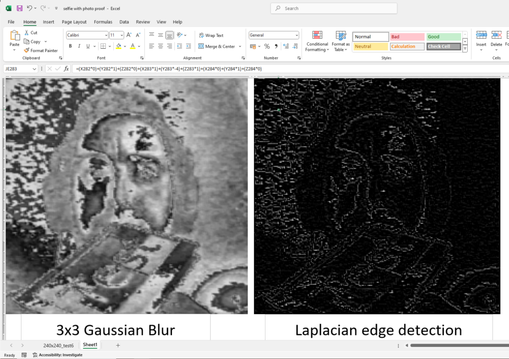
KERNEL CONVOLUTIONS! YAY!
Microsoft excel makes the creation and propagation of a kernel very easy. The below images show the results after two successive kernel convolutions; the first using a 3×3 Gaussian Blur to smooth the image and subsequently applying a 3×3 Laplacian edge detection.
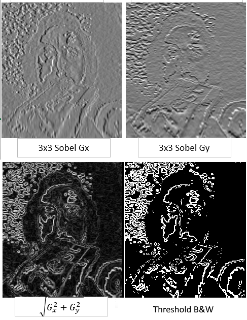
The below image is more kernel convolutions, this time using the Sobel edge detection kernels.
Conclusion
The elation I felt after this worked was simply joyous. This was meant to be a quick side-project, but ended up being a massive multiple-week headache. I’m glad to have gained new skills and I hope to be able to apply them in future projects.
I hope this post has been informative.